General technical description, Plug-on transmitter, Uh190 block diagram – Lectrosonics UH190 User Manual
Page 3: Rio rancho, nm – usa 3
Plug-on Transmitter
GENERAL TECHNICAL DESCRIPTION
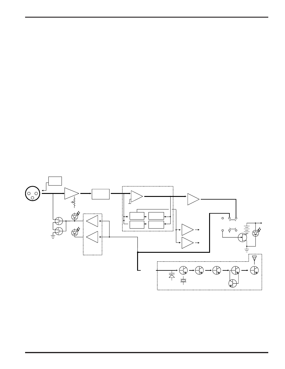
The UH190 transmitter is comprised of a number of functional subsystems as shown in the block diagram below.
The 190 system uses 15kHz deviation. The transmitter circuits are all regulated to allow full output power from the
beginning (9 Volts) to the end (7 Volts) of battery life. The oscillator crystal is shock mounted to provide ruggedness.
The input amplifier uses a Motorola 33078 op amp for ultra low noise operation. It is gain controlled with a wide
range input compressor which cleanly limits input signal peaks over 40dB above full modulation.
Traditionally, compandors have been a source of distortion in wireless microphone systems. The basic problem with
conventional systems is that the attack and decay times are always a compromise. If the time constants are fast,
high frequency transients will not be distorted, but this will cause low frequency distortion. If the time constants are
slower, low frequency audio distortion will be low, but high frequency transients will then be distorted. The 190
system introduces an entirely new approach to solving this basic problem, called “dual-band companding.”
There are actually two separate compandors in the 190 system, one for high frequencies and one for low frequen
cies. A crossover network separates the frequency bands at 1kHz with a 6dB per octave slope, followed by separate
high and low frequency compandors. The attack and release times in the high frequency compandor are fast enough
to keep high frequency transient distortion at a low level, and the low frequency compandor uses slower time con
stants, reducing low frequency distortion to well below that of a conventional compandor.
MIC
JACK
+5V BIAS
Vref
BASS
TREBLE
LP FILTER
HP FILTER
SET
LED
LIMIT
LED
COMPANDOR
Vreg
Vreg
+5VDC
+3.6VDC
COMPANDED
AUDIO
XTAL OSC
X4
X2
X2
X2
UHF TRANSMITTER
+9VDC
PWR
LED
SHUNT
LIMITER
-9V
ON
MUTE
OFF
SUPPLY
INPUT
AMP
AUDIO
LEVEL
LP
FILTER
PEAK AUDIO
INDICATOR &
LIMITER
DRIVER
UH190 Block Diagram
Rio Rancho, NM – USA
3