General technical description, Vhf hand-held transmitter, T187 block diagram – Lectrosonics T187 User Manual
Page 3
VHF Hand-held Transmitter
GENERAL TECHNICAL DESCRIPTION
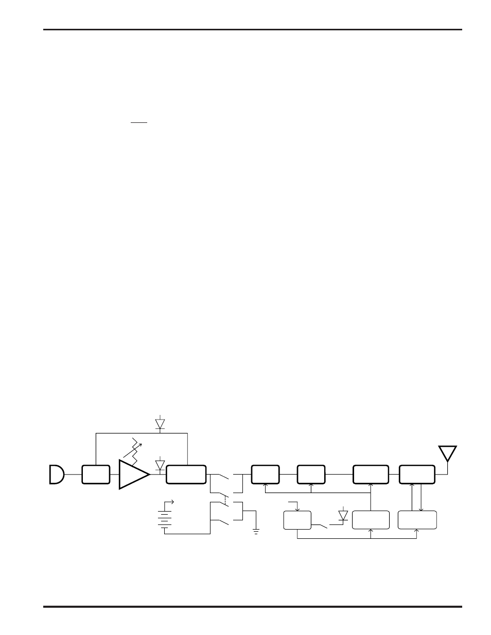
The T187 transmitter is comprised of a number of functional sub-systems as shown in the block diagram below. It is
offered with a variety of popular dynamic and electret microphone capsules from Shure, Electro-Voice and others for
various applications.
The limiter is a low distortion shunt FET compressor operating before the mic preamp. Control signals for the
compressor are derived after the mic preamp to eliminate any possibility of overload under any signal input condition
up to a maximum of 30 Volts input. The range of limiting action before distortion occurs is 20 dB. Audio signal level
and compressor action are indicated by LEDs visible under the battery cover door, next to the gain control.
The mic preamp is an ultra-low noise NE5534 type op-amp. The gain control, accessed by removing the battery
door, is semi-logarithmic to provide smooth action. Aside from gain control, this stage also adds high frequency pre-
emphasis to the audio signal, to provide a 10 dB signal-to-noise ratio improvement. The receiver provides matching
de-emphasis to insure the highest signal-to-noise ratios under varying RF signal conditions.
The T187 audio section includes a 2:1 compandor noise reduction circuit compatible with all Lectrosonics 185 Series
VHF receivers. This compandor compresses (“encodes”) the dynamic range by reducing it 2:1 in the transmitter
audio signal. Complementary circuitry in the receiver restores (“decodes”) the original full dynamic range of the
signal by expanding it 1:2.
There are two operating switches located on the bottom panel. One is for power on/off and the other is an audio
mute. These operating switches can be bypassed for applications where the user should not have access to them.
The RF transmitter section is composed of a crystal stabilized main oscillator followed by a frequency tripler and two
frequency doublers. The crystal controlled frequency is extremely stable over a wide temperature range and over
time. All three oscillator stages are double tuned. Double tuning provides higher attenuation of spurious emissions
which, in turn, minimizes the possibility that the transmitter RF output would interfere with another transmitter/
receiver system operating in the same vicinity.
All RF stages are biased from a regulated internal power supply. The output stage has a separate feedback regula
tor which not only stabilizes its operating point, but also minimizes AM distortion. These regulators keep the RF and
audio performance consistent from the beginning (9 Volts) to the end (6.5 Volts) of battery life.
PRE
AMP
TRIPLER
DOUBLER
COMPANDOR
LIMIT
LED
LIMITER
+9V IN
+9V OUT
AUDIO
BYPASS
BYPASS
POWER
ON/OFF
CAPSULE
-10dB
LED
9 VOLT
BATTERY
OSC.
(VXO)
BATT
SENSOR
POWER
LED
DOUBLER
VOLTAGE
REGULATOR
FEEDBACK
REGULATOR
INTERNAL
ANTENNA
MIC
T187 Block Diagram
Rio Rancho, NM – USA
3