Mic jack, Audio level, Modulation leds – Lectrosonics MM400b User Manual
Page 9: Frequency select switches, Antenna
Watertight Miniature UHF Belt-Pack Transmitter
Mic Jack
The Mic Jack is a 2.5 mm microplug that is wired to
accommodate two-wire positive bias lavalieres. While
the M152-WP (waterproof) is specifically designed for
the MM400B, other two-wire lavaliere microphones can
be adapted to the MM440B using the WPMC-3 or
WPMC-10 kits. A Switchcraft 850 connector (Lec
trosonics P/N 21357) can be used in an emergency
though it is not waterproof. (See Replacement Parts
and Accessories.)
The equivalent input circuit wiring for the Mic Jack is
shown below:
2k
6V Mic Bias
Mic
Jack
330pF
330pF
FB
FB
100
2k
30uF
2k
2.2nF
To Mic Amp
Audio Level
The Audio Level Control is used to adjust the audio
input level from the microphone for proper modulation
of the output signal from the transmitter.
Modulation LEDs
The two bicolor Modulation LEDs provide a visual
indication of the audio signal level input from the
microphone. These LEDs can glow either red or green
to indicate modulation levels as shown in the following
chart.
Signal Level
-20 LED
-10 LED
Less than -20 dB
Off
Off
-20 dB to -10 dB
Green
Off
-10 dB to +0 dB
Green
Green
+0 dB to +10 dB
Red
Green
Greater than +10 dB
Red
Red
When the Power ON/OFF Switch is configured for Audio
Mute Mode, the -10 Modulat ion LED is also used to
indicate if the transmitter is in an audio muted, or an
unmuted condition. In Audio Mute Mode, if the Power
ON/OFF switch is set to OFF, the transmitter remains
powered up; however, the audio is muted and the -10
Modulation LED blinks green.
If the Power ON/OFF switch is set to ON and the switch
is configured for Audio Mute Mode, -10 and -20 LEDs
operate normally to indicate audio level.
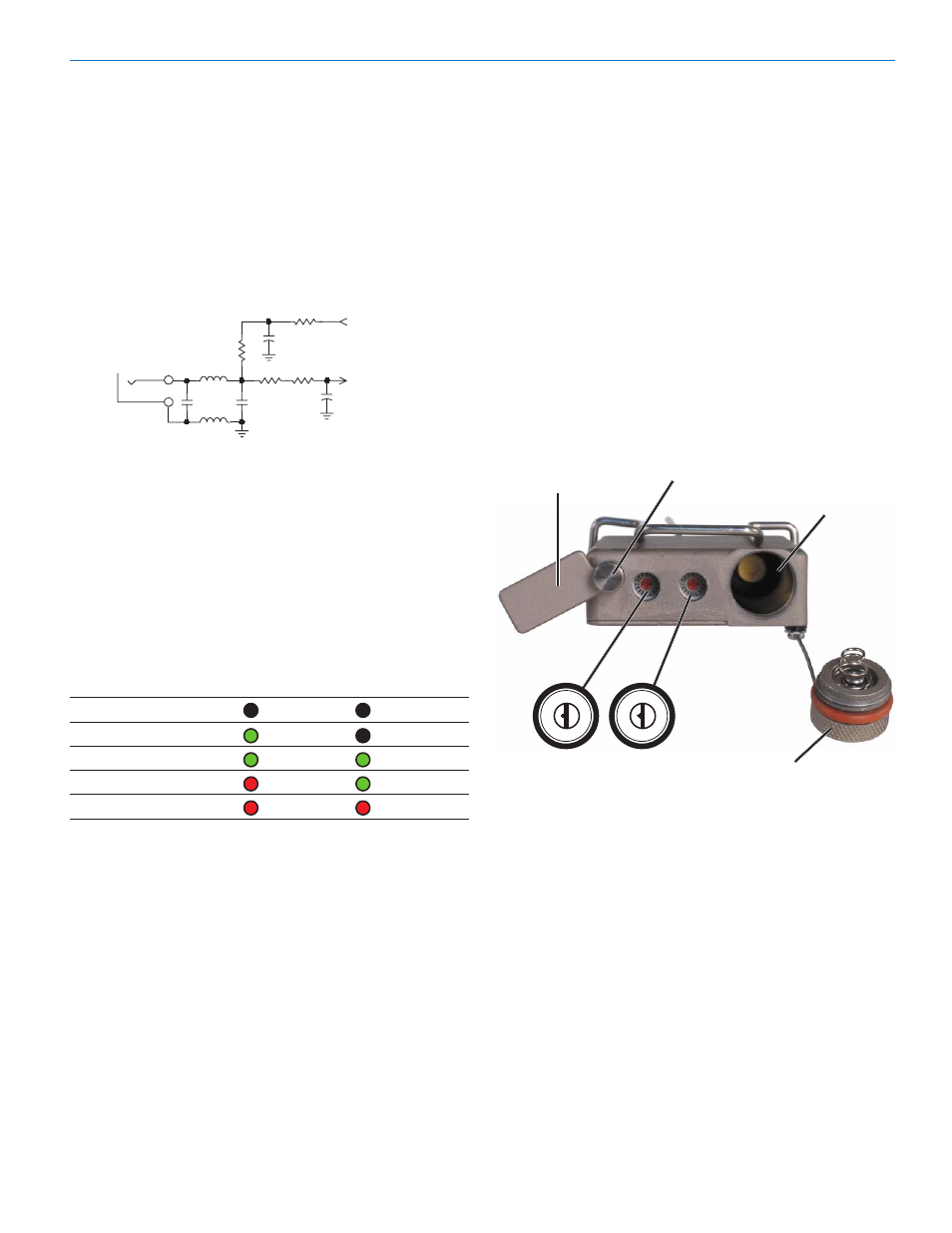
Frequency Select Switches
Two 16-position rotary Frequency Select Switches are
used to select the operating frequency, for setting
Compatiblity Modes and for configuring the Power ON/
OFF switch.
The switches are accessed by loosening the retaining
screw holding the cover plate, lifting the cover away
from the housing and rotating it to expose the switches.
For setting the operating frequency, the left switch
(1.6MHz) adjusts the operating frequency up or down in
1.6 MHz increments. The right switch (100kHz) adjusts
the frequency up or down in 100 kHz increments. (See
Operating Instructions, Adjusting the Transmitter
Frequency.)
A sequence of Frequency Select Switch settings and
Power ON/OFF toggles are used to set Compatibility
Modes and for configuring the Power ON/OFF switch.
(See
Operating Instructions, Setting Compatibility
Modes and Power Switch Function Selection.)
Frequency Switch
Frequency Switch Cover Plate
Frequency Select Switches
Retaining Screw
Cover Plate
Battery
1.6M
100K
Battery Compartment
0 1
2
3
4
5
6
7
8
9
A
B
C
D
E
F
0 1
2
3
4
5
6
7
8
9
A
B
C
D
E
F
Compartment Cap
Antenna
The flexible steel cable antenna supplied with the
transmitter is cut to 1/4 wavelength of the center of the
frequency block (the frequency range) of the transmitter.
It is mounted with an SMA connector. The SMA con
nector is a 50 Ohm RF port which can also be con
nected directly to test equipment.
Replacement antennas are available in pre-cut lengths
for specific frequency blocks, or as a kit with instruc
tions to cut the antenna for any frequency block. (See
Replacement Parts and Accessories.)
Rio Rancho, NM
9