General technical description – Lectrosonics M185 User Manual
Page 3
GENERAL TECHNICAL DESCRIPTION
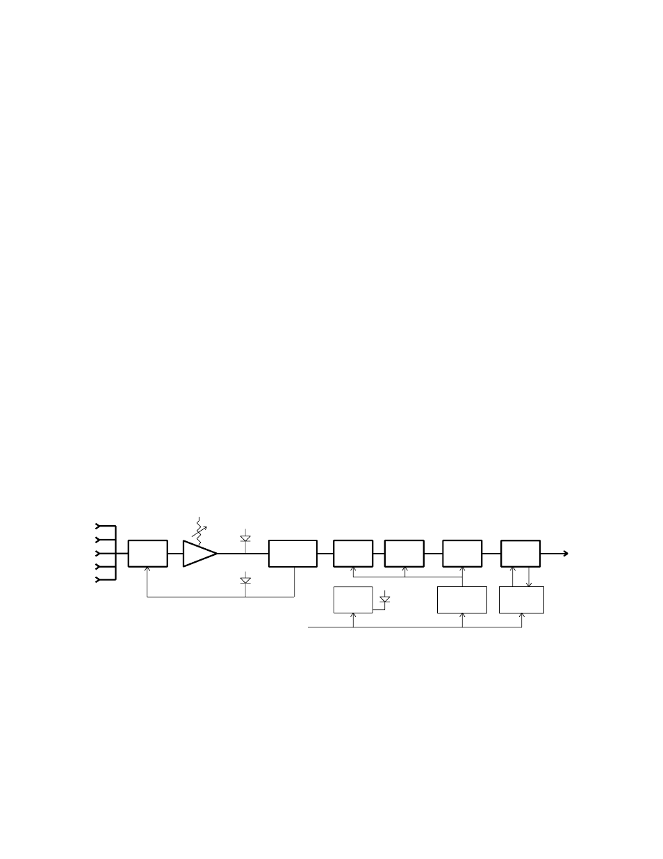
The M185 transmitter is comprised of four major functional subsystems: the input compressor, the mic
preamp/gain control, the compandor, and the RF transmitter (see block diagram below).
The input compressor is a low distortion shunt FET compressor operating before the mic preamp.
Control signals for the compressor are derived after the mic preamp to eliminate any possibility of
overload under any signal condition up to a maximum of 30 Volts input at the pin 5 (line level) input
tap. The range of limiting action before distortion occurs is 20 dB. Audio signal level and compressor
action are indicated by two LEDs on the control panel.
The mic preamp is an ultra-low noise NE5534 type op-amp. Aside from gain control, this stage also
adds high frequency pre-emphasis to the audio signal. This insures the highest signal-to-noise ratios
under varying signal conditions. The gain control is semi-logarithmic to provide smooth action.
The M185 audio section includes a compandor circuit compatible with Lectrosonics 185 Series VHF
receivers. This compandor compresses the dynamic range by 2 to 1. A complementary system in the
receiver expands the original dynamics 1 to 2 for full audio quality. Compression and expansion ratios
are fully complementary. High frequency pre-emphasis is implemented in the transmitter to provide
another 10 dB signal-to-noise ratio improvement. Matching de-emphasis is provided in the receivers.
The RF transmitter is composed of a crystal stabilized main oscillator followed by a frequency tripler
and two frequency doublers. All three stages are double tuned. Double tuning provides high
attenuation of spurious signals, which in turn minimizes the possibility that a transmitter would interfere
with another transmitter/receiver system on another frequency.
All RF stages are biased from a regulated internal power supply. The output stage has a separate
feedback regulator which not only stabilizes its operating point, but also minimizes AM distortion.
These regulators keep the RF and audio performance consistent from the beginning (9 Volts) to the
end (6.5 Volts) of battery life.
Schematics and alignment instructions will be provided to qualified repair personnel upon request.
LIMITER
20 dB
MIC PREAMP
LIMIT
LED
LEVEL
LED
COMPANDOR
(VCO)
+9V IN
45MHZ
90MHZ
180MHZ
1
2
3
4
5
15 MHZ XTAL
OSCILLATOR
BATTERY
SENSOR
CIRCUIT
POWER
LED
FREQ.
TRIPLER
FREQ.
DOUBLER
VOLTAGE
REGULATOR
FEEDBACK
REGULATOR
FREQ.
DOUBLER
RF
OUT
Figure 1 - M185 Block Diagram
2