Input limiter, No pre-emphasis/de-emphasis, Pilot tone squelch – Lectrosonics LM User Manual
Page 5: Wide-band deviation, Long battery life, Frequency agility, Antenna, Block diagram
Frequency-Agile UHF Belt-Pack Transmitter
Input Limiter
The transmitters employ a digitally-controlled analog
audio limiter prior to the analog-to-digital converter. The
limiter has a range greater than 30 dB for excellent
overload protection. A dual release envelope makes
the limiter acoustically transparent while maintaining
low distortion. It can be thought of as two limiters in
series, connected as a fast attack and release limiter
followed by a slow attack and release limiter. The limiter
recovers quickly from brief transients, so that its action
is hidden from the listener, but recovers slowly from
sustained high levels, to both keep audio distortion low
and preserve short term dynamic changes.
No Pre-Emphasis/De-Emphasis
Because the signal to noise ratio of the hybrid system is
so high, there is no need for conventional pre-emphasis
(HF boost) in the transmitter and de-emphasis (HF roll
off) in the receiver. Thus, the possible distortion prob
lems associated with pre-emphasis and de-emphasis
are eliminated.
Pilot Tone Squelch
The hybrid system uses one of 256 different ultrasonic
tones between 25 and 32 kHz, that modulate the carrier
to operate the receiver squelch. The pilot tone fre
quency is chosen according to which of the 256 chan
nels has been selected by the frequency switch setting.
The benefit of a pilot tone squelch system is that the
receiver will remain muted until it receives the pilot tone
from the matching transmitter, even if a strong RF
+5V Bias
signal is present on the carrier frequency of the system.
The 400 Series extends this concept even further by
insuring that all transmitters in a system have different
pilot tone frequencies so that even spurious RF from
the wrong transmitters can’t open the receiver squelch.
Wide-Band Deviation
By employing ±75 kHz diviation, Lectrosonics dramati
cally improves the capture ratio, signal to noise ratio
and AM rejection of our wireless system.
Long Battery Life
The use of switching power supplies throughout the
design allows over 6 hours of operation using a single 9
volt alkaline battery and over 13 hours of operation with
a 9 volt lithium battery. The battery contacts are spring
loaded to prevent “rattle” as the unit is handled.
Frequency Agility
The transmitter section uses a synthesized, frequency
selectable main oscillator. The frequency is extremely
stable over a wide temperature range and over time.
Two rotary switches, located on the side panel of the
unit, provide 256 frequencies in 100 kHz steps over a
25.5 MHz range. This alleviates carrier interference
problems in mobile or traveling applications.
Antenna
The antenna consists of a permanently attached
flexible, unbreakable 1/4 wavelength galvanized steel
cable.
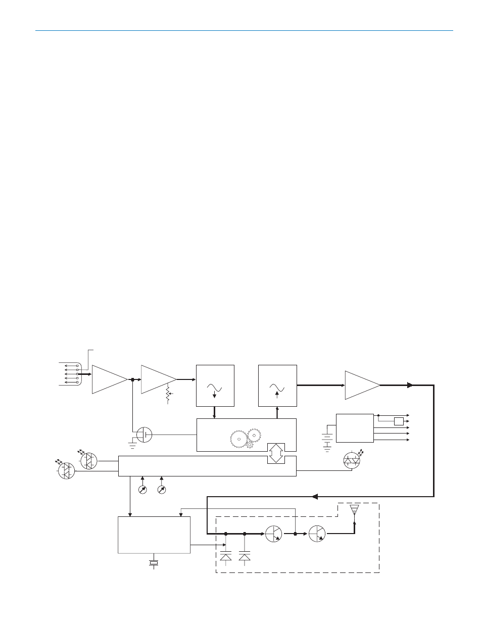
Block Diagram
Phase Locked Loop
Voltage
Controlled
Oscillator
Freq
Switches
11001001
A-D
Converter
Digital Signal Processor
11001001
D-A
Converter
Shunt
Limiter
Bicolor
Modulation
LEDs
Microprocessor
9V
Battery
Switching
Power
Supply
+3.3v
+1.8v
+9v
-3v
Hi/Lo
Pass
Filter
Audio
Encoded
Audio +
Pilot Tone
11.3 MHz
Reference
Bicolor
Power
LED
Audio
Level
Input
Amp
Final
Amplifier
Supply
5
4
3
2
1
Mic
Jack
+5v
<--See
5-Pin Input Jack Wiring for details.
Rio Rancho, NM
5