Antenna power jumpers – Lectrosonics UMC16b User Manual
Page 4
UMC16B
LECTROSONICS, INC.
4
RF OUT
12V DC IN
400MA MAX
RF OUT
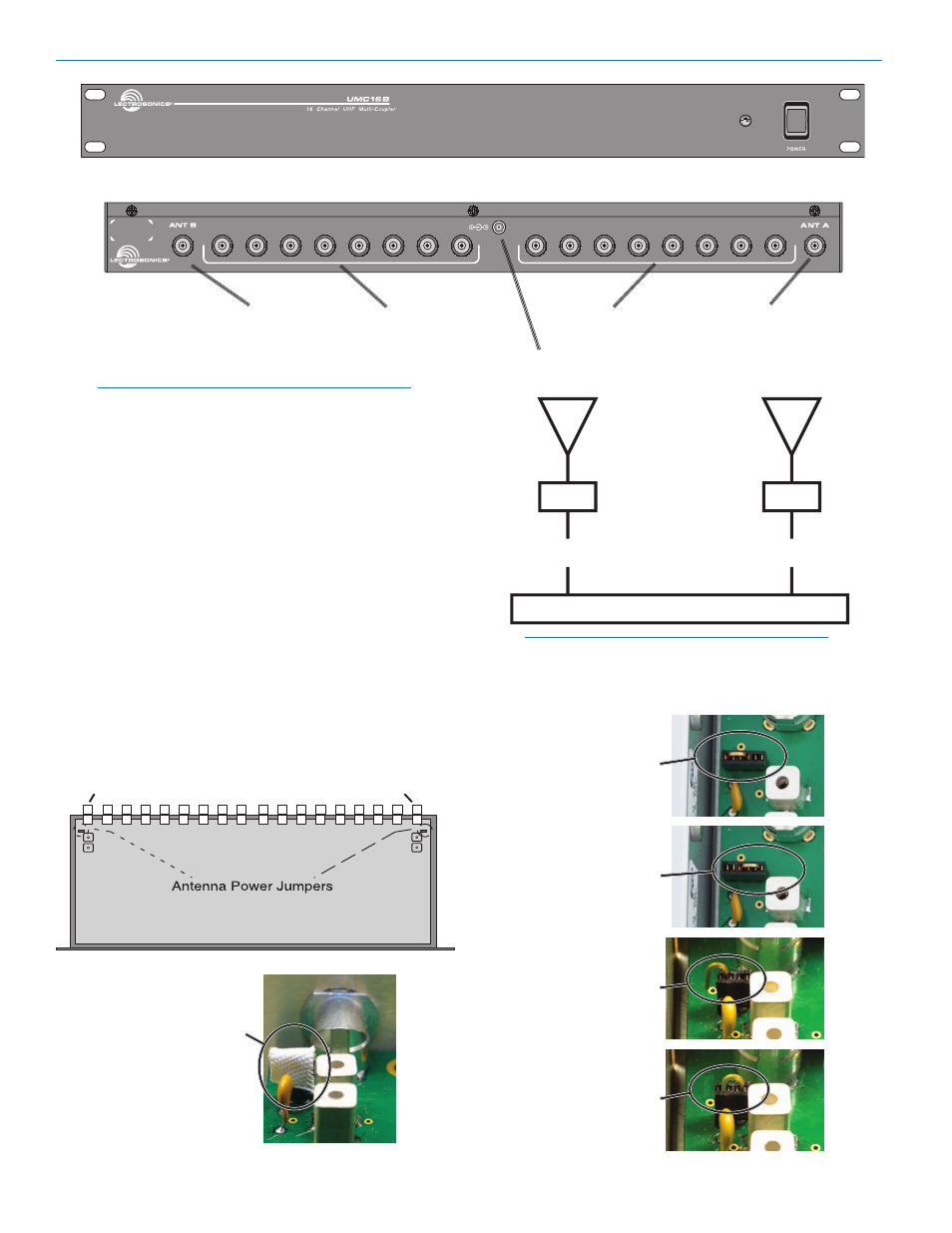
UMC16B Front Panel
UMC16B Rear Panel
Antenna Power Jumpers
NOTE: These jumpers are
ONLY to be used when
the Lectrosonics UFM50 or UFM230 filter/amp
modules are being powered from DC on the
antenna input jacks on the UMC16B multicoupler.
For long cable runs between the UMC16B and remote
antennas, gain must be applied at the antenna end of
the coaxial cable to compensate for the loss that oc-
curs over the length of the cable run. The Lectrosonics
UFM230 or UFM50 filter/amp module can be placed in
an optimum position close to the antenna and powered
by DC from the UMC16B via the coaxial cable. This
applies the gain before the loss in the coaxial cable run
to maximize the signal to noise ratio. Jumpers at the
antenna inputs on the UMC16B enable the DC power
on the BNC jacks.
1. To enable the DC antenna power, unplug the power
cord and remove the cover
(12 screws).
2. Locate the jumpers on the circuit board. When the
jumper is inserted toward the outside of the unit, power
is disabled. Inserted toward the inside of the unit, power
is enabled.
Antenna A input
50 ohm BNC
Antenna B input
50 ohm BNC
RF outputs x 8
50 ohm BNC
RF outputs x 8
50 ohm BNC
DC power input
12 to 18 VDC
NOTE: If a splitter/combiner is used between the
UFM230 and the UMC16B, it will not pass the DC
power to the antennas.
Long coaxial cable
Long coaxial cable
UFM230
UFM230
UMC16B
Antennas
Triple socket
jumper toward
outside to disable
antenna power
Triple socket
jumper toward
inside to enable
antenna power
ANT A
ANT B
Double socket
jumper toward
outside to disable
antenna power
Double socket
jumper toward
inside to enable
antenna power
If tape is present
over the socket,
be sure to
replace it after
re-positioning
the jumper