Antenna use and placement, Reflective surface, Multi-path dropout – Lectrosonics UDR300c User Manual
Page 17: Wireless diversity receiver, Transmitter, Receiver, Di rect si gnal, Rio rancho, nm – usa 17
Wireless Diversity Receiver
ANTENNA USE AND PLACEMENT
When using a remote antenna with this receiver, position the
antennas at least three or four feet apart and so that they are
not within 3 or 4 feet of large metal surfaces. If this is not
possible, try to position the antennas so that they are as far
away from the metal surface as is practical. It is also good to
position the receiver so that there is a direct “line of sight”
between the transmitter and the receiver antenna. In situa
tions where the operating range is less than about 100 feet,
the antenna positioning is much less critical. The antennas
can also be configured with one whip mounted directly onto
the rear panel of the UDR300C receiver, and the other one
mounted remotely.
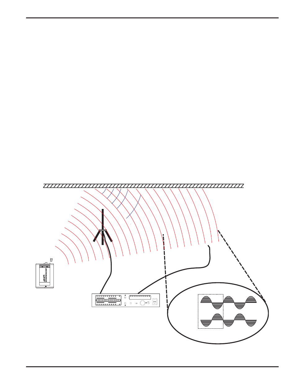
A wireless transmitter sends a radio signal out in all directions.
This signal will often bounce off nearby walls, ceilings, etc. and
a strong reflection can arrive at the receiver antenna along
with the direct signal. If the direct and reflected signals are out
of phase with each other a cancellation may occur. The result
would be a “dropout.” A dropout sounds like either audible
noise (hiss), or in severe cases, may result in a complete loss
of the carrier and the sound when the transmitter is positioned
in certain locations in the room. A dropout normally sounds
like “hiss” or a “swishing” sound. Moving the transmitter even a
few inches will change the sound of the hum or hiss, or elimi
nate it. A dropout situation may be either better or worse as
the crowd fills and/or leaves the room, or when the transmitter
or receiver is operated in a different location.
The UDR300C receiver offers a sophisticated diversity design
which overcomes dropout problems in almost any imaginable
situation. In the event, however, that you do encounter a
dropout problem, first try moving the antenna at least 3 or 4
feet from where it was. This may alleviate the dropout problem
on that antenna. If dropouts are still a problem, try moving the
antenna to an entirely different location in the room or moving
the antennas in closer to the transmitter location. By observ
ing the OPTI-BLEND LEDs on the front panel, you can deter
mine which antenna is suffering weak signals.
Lectrosonics transmitters radiate power very efficiently, and
the receivers are very sensitive. This reduces dropouts to an
insignificant level. If, however, you do encounter dropouts
frequently, call the factory or consult your dealer. There is
probably a simple solution.
REFLECTIVE SURFACE
DI
RECT SI
GNAL
TRANSMITTER
DIRECT SIGNAL
INDIRECT SIGNAL
PHASE
CANCELLATION
OPTI
BLEND
OPTI
BLEND
TX AUDIO LEVEL dB
RF LEVEL
RF LEVEL
LECTROSONICS
FREQ
SELECT
POWER
MONITOR
MODE
MENU
6 1 5 . 1 T X : B 3 T V 2 3
RECEIVER
MULTI-PATH DROPOUT
Rio Rancho, NM – USA
17