General technical description, Uhf wireless diversity receiver, Diversity reception – Lectrosonics UCR200d User Manual
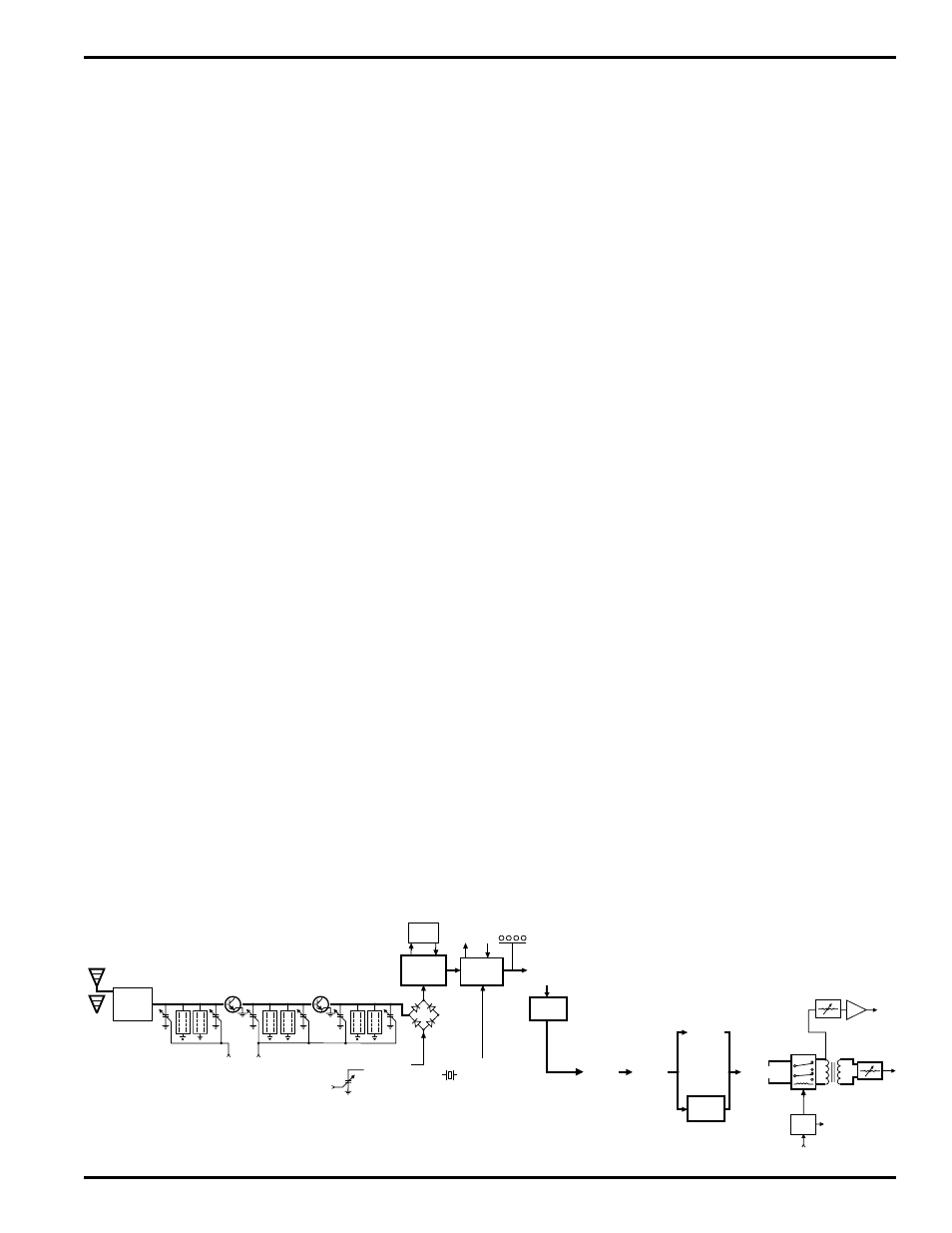
Page 3: Frequency tracking front-end, High current low noise amplifiers, Double balanced diode mixers, Rio rancho, nm – usa 3, Ucr200d block diagram
UHF Wireless Diversity Receiver
GENERAL TECHNICAL DESCRIPTION
The UCR200D is a portable, high performance, dual-conversion,
frequency synthesized, UHF receiver. The RF performance is
extremely stable over a very wide temperature range, making the
UCR200D perfectly suited to the rough environmental conditions
found in the field. The proprietary audio processing includes a
dual-band compandor for very low distortion and a superior signal
to noise ratio. The squelch system is operated by a separate pilot
tone and mutes the audio output directly at the output connector.
The audio output is calibrated for exact level matching, with a ten
LED bar graph meter.
DIVERSITY RECEPTION
The antenna phase switching diversity technique was chosen in
order to keep the receiver compact enough for camera mounted or
shoulder bag applications. This diversity reception technique
effectively minimizes dropouts in short range situations where
multi-path reflections can cause serious problems. The optimum
diversity reception is realized with the diversity antenna placed
away from the receiver, however, dropouts are significantly re
duced with two antennas mounted directly on the receiver.
RF SECTION
The problem posed to the design staff was to retain the RF reliabil
ity of the Lectrosonics’ fixed frequency designs but add the
flexibility of a frequency agile design. The universal (and poor)
way to build frequency agile systems is to design a wide open
front end that will pass any frequency within the tuning range of
the system. This leads to very poor RF performance with lots of
interference, driving the user to switch frequencies in an attempt to
sidestep the interference. This makes frequency agile receivers a
self fulfilling system; you have to use the frequency agility to get
away from the problems caused by the frequency agile design
compromises.
The problem of frequency agility is further compounded when you
realize that frequency changes “on the fly” cannot be made on any
type of wireless system. For example, if there is suddenly an
interference problem with a system in use, on stage for instance, a
frequency change cannot be made without interrupting the pro
gram. Basically, the show must go on. In multi-channel
applications, changing the frequency of one system will usually
produce all kinds of new intermodulation problems with the other
systems operating in the same location. Frequency agility is not
the universal panacea for interference problems. It is only another
tool and a limited tool at that. The first line of defense must be the
system’s basic immunity to interference. That required a new look
at frequency agile receiver design.
FREQUENCY TRACKING FRONT-END
Our solution to the wide open front end problem was to design a
selective front end that can be tuned to the frequency in use. Since
we wanted this front end to be equivalent to our fixed frequency
front ends, this was a daunting task. Lectrosonics has always used
front ends with more sections and much more selectivity than any
other wireless manufacturer. The final design consisted of a total
of 6 transmission line resonators with variable capacitance applied
to each resonator by the hexadecimal switches. This allows each
resonator to be individually tuned by the hexadecimal switches for
any user selected frequency in a 25 MHz band.
This sophistication produced a front end that was as selective as
fixed frequency designs, yet could cover the entire 25 MHz range.
The next step to improve the front end was to use good old
fashioned “brute force.”
HIGH CURRENT LOW NOISE AMPLIFIERS
The gain stages in the front end use some rather special transistors
in a feedback regulated high current circuit that combine three
parameters that are generally at odds with one another. These are:
low noise, low gain and relatively high power. It is easy to
understand the advantages of low noise and high power capability
but why is low gain desirable? The answer is that in a receiver,
low gain allows the front end to handle stronger RF signals with
out output overload, which is “increased headroom,” so to speak.
The result of a design that takes all three of these parameters into
consideration at once, is a low noise RF amplifier with a sensitiv
ity rating equal or better than the best conventional design with a
hundred times less susceptibility to intermodulation interference.
Combining the high power gain stages with the tracking front end
produces a receiver that is unusually immune to single and mul
tiple interfering signals close to the operating frequency and in
addition strongly rejects signals that are much farther away.
DOUBLE BALANCED DIODE MIXERS
In all wireless receivers, a mixer is used to convert the carrier
frequency to the IF frequency where most of the filtering and gain
in the receiver takes place. After doing all the right things in the
FILTER
AMP
1ST
LOCAL
OSCILLATOR
455KHZ
BP
FILTER
2:1
EXPANDER
TREBLE
2:1
EXPANDER
BASS
23 KHZ
LP
FILTER
HEADPHONE
OUT
OUTPUT
LEVEL
ADJUST
XLR
OUT
PILOT
TONE
MUTE
FILTER
uP
AMP
FILTER
HI-LEVEL
DIODE MIXER
RF MODULE
2ND MIXER
&
IF AMP
50KHz
LP FILTER
XTAL
CONTROLLED
2ND
OSCILLATOR
RF LEVEL
LEDs
SAW
FILTER
70 MHz
IF AMP
COUNTING
DETECTOR
AUDIO
AMP
UCR200D
BLOCK DIAGRAM
uP
uP
VARIABLE
CUT-OFF
LP FILTER
TO DATA
DISPLAY
ANTENNA
SWITCHING
uP
Rio Rancho, NM – USA
3