Front panel controls and functions – Lectrosonics DR175NC User Manual
Page 3
FRONT PANEL CONTROLS AND FUNCTIONS
MODULATION INDICATORS Two (2) LEDs indicate the audio level (modulation) of the incoming signal, which are
typically used for proper adjustment of the transmitter’s "MIC LEVEL" or "GAIN". The -20 LED (green) lights during
normal modulation. The 0dB (red) LED indicates maximum modulation and that the transmitter audio input may be
"limiting." Occasional flickering of this LED is normal. It should not stay on for long periods, however.
OFF/ON This switch turns the receiver power off and on.
CODE Not active on this model (DR175NC.)
OPTI-BLEND LEDs The audio outputs of two separate receivers are mixed together in a "ratio" that is regulated
by comparing the signal to noise ratios in the two receivers. The mixture ratio of the two audio signals is indicated
on the front panel by two LEDs that vary in brightness. As a build-up of noise occurs in one receiver, the
corresponding LED for that receiver dims or goes out as the circuitry pans to the other receiver. Since the mixture
ratio of the two audio signals is determined by a comparison of their signal to noise ratios, the "blending" action
occurs regardless of how strong (or weak) the incoming RF signals are. This is the distinct advantage of this
receiver design over any other type of diversity system available.
AUDIO LEVEL This control knob adjusts the audio level of the XLR output on the rear panel.
OPTI-BLEND
OFF
ON
AUDIO LEVEL
POWER
A
B
20 0dB
CODE
LECTROSONICS
MODULATION
GRN
RED
GRN
GRN
RED
YEL
RATIO
DIVERSITY
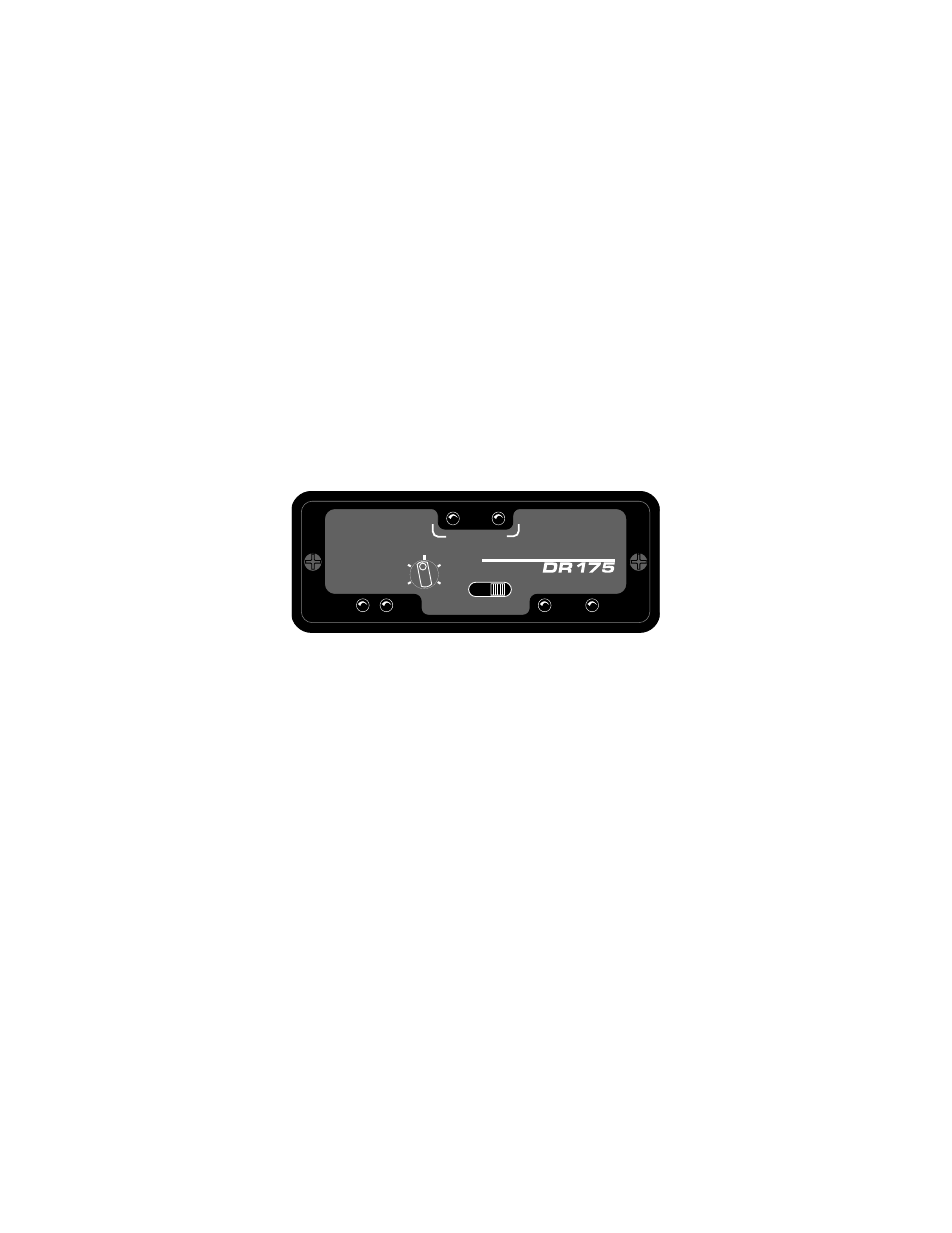
Figure 1 - DR175NC Front Panel
3