Operating instructions, Selecting the compatibility mode – Lectrosonics LMa User Manual
Page 8
LMa
LECTROSONICS, INC.
8
0 1
2
3
4
5
6
7
8
9
A
B
C
D
E
F
0 1
2
3
4
5
6
7
8
9
A
B
C
D
E
F
Attaching a Microphone or Musical
Instrument and Adjusting Audio Levels
The front panel Modulation LEDs indicate input level
and limiter activity. (See Modulation LED Signal Level
Table.) Since the distortion introduced by the limiter is
minimal and full modulation is assured, occasional red
flickering of the -20 LED is desirable.
Different voices or instruments will usually require dif-
ferent settings of the AUDIO LEVEL control, so check
this adjustment as each new person uses the system.
If several different people will be using the transmitter
and there is not time to make the adjustment for each
individual, adjust it for the loudest voice.
Musicians also vary their volume depending on the na-
ture of the music. It is suggested that the transmitter be
adjusted for the passage with the loudest volume.
1) If necessary, install a fresh battery.
2) Insert the 5-pin into the input jack. Ensure the pins
are aligned and the connector locks in (it will click).
For those using a musical instrument, insert the 1/4
inch plug on the other end of the instrument cable
into the appropriate jack on your musical instru-
ment.
3) Mute the main sound system or amplifier and rotate
the AUDIO LEVEL control on the transmitter to
maximum counterclockwise (Off).
4) Set the transmitter Power switch to ON.
5) For microphone users, position the microphone in
the location where it will be used in actual opera-
tion.
For musicians, adjust the instrument volume con-
trols to the highest levels that would be used during
a performance.
Selecting the Compatibility Mode
The LMa transmitter is capable of working with Lec-
trosonics 400 Series Digital Hybrid Wireless
®
, 200
Series analog, 100 Series analog and some non-Lec-
trosonics analog wireless receivers (contact the factory
for details). The transmitter must be set to the operating
mode of the matching receiver, which is easily done us-
ing the supplied screwdriver and a battery.
NOTE: The unit is supplied from the factory as a
400 series transmitter.
1) Ensure the battery is good.
2) Turn OFF the transmitter.
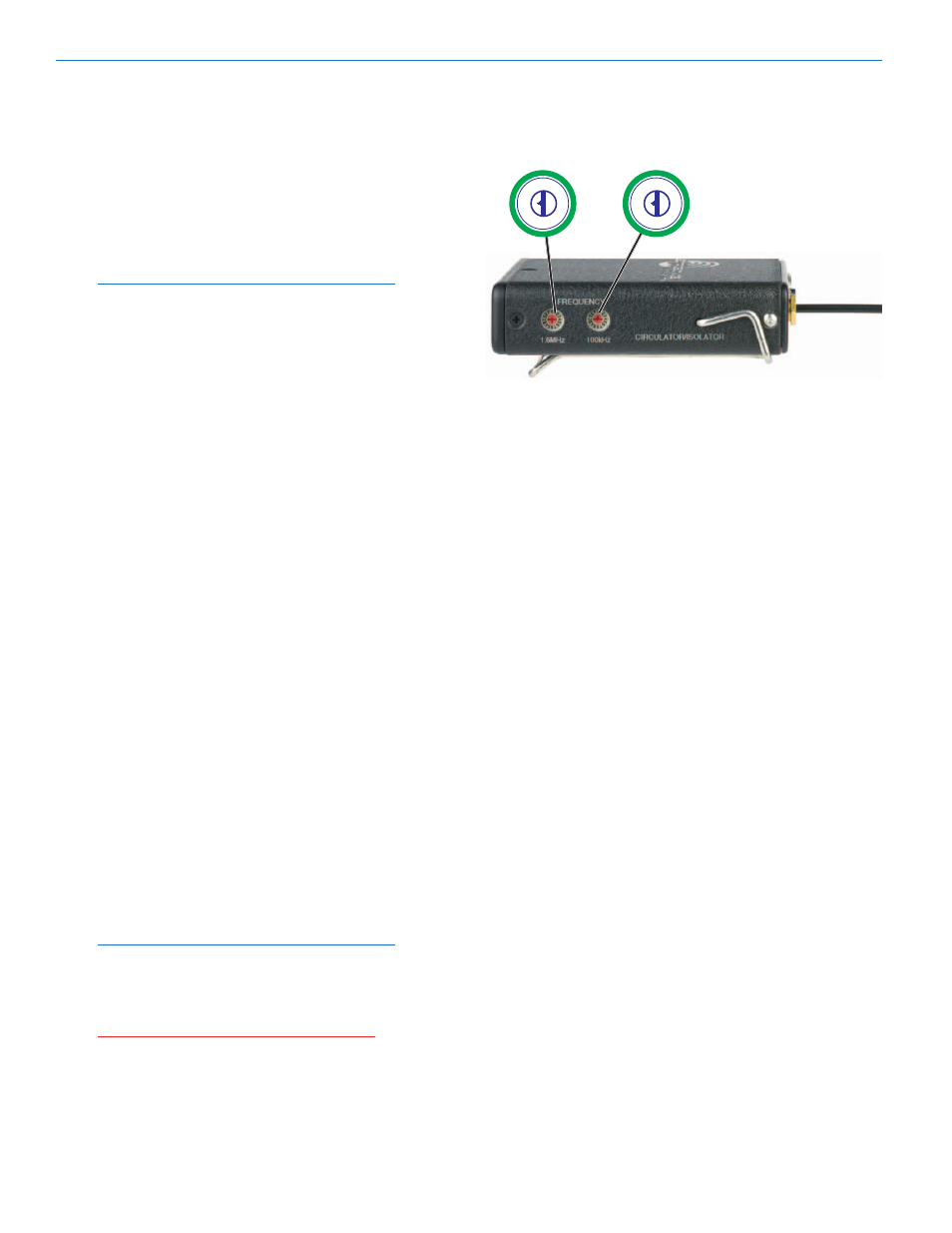
3) With a small screwdriver (one is included with your
unit), set the Frequency Select Switches to CC. (for
Change, Change).
4) Toggle the power switch ON briefly – just long
enough for the LED’s to light up and then turn it
OFF.
5) Change the Frequency Select Switches to one of
the following settings:
• 100 Series mode:
1,1
• 200 Series mode:
2,2
• Mode 3:
3,3
• 400 Series mode:
4,4
• IFB Series mode:
5,5
• Mode 6:
6,6
6) Toggle the power switch ON, then OFF again.
7) Change the Frequency Select Switches to 0,0.
8) Turn the transmitter ON to complete the operation.
The LEDS will blink to indicate the selected com-
patibility mode. Immediately after power up, all
LEDs will blink together red, then green, followed
by the audio level LEDs (-20 and -10) blinking to
indicate the mode.
The LEDs will blink:
• Once for 100 Series mode
• Two times for 200 Series mode
• Three times for some other receivers
• Four times for 400 Series mode
• Five times for IFB mode
• Six times for Mode 6
Note: Each time the transmitter is turned on, the
Modulation LEDs will confirm the current operating
mode with the number of blinks listed in Step 2.
The mode setting will not change until it is reset
with the procedure listed above.
Attention: During the procedure to set the
compatibility mode, each step between toggles
of the power switch must be performed within
ten seconds, or the procedure must be started
from the beginning.
Operating Instructions
Frequency Select Switch Settings (C,C)
1.6M 100K