Hg5421g_install_3.pdf, Installation instructions – L-com HG5421G User Manual
Page 3
IP-00053 Rev. D – 02/07 Page 3 of 3
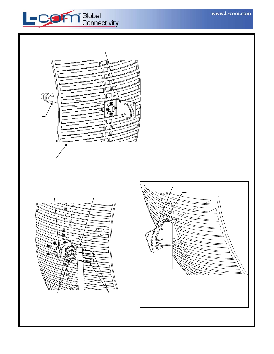
Position the “L” Bracket to the back of the Grid
Assembly, noting the orientation required for the
desired polarity.
Position the Feed Horn to the front of the Grid
Assembly, again noting the orientation required
for the desired polarity.
Secure the Feed Horn & “L” Bracket to the Grid
Assembly using (4) #M5 machine screws with
lock washers, flat washers and nuts.
Installation Instructions
Feed Horn
Antenna Grid
“L” Bracket
Install the (2) Mast Clamps on the U-Bolts as shown
and fasten to the “L” Bracket using (4) lock washers
and (4) Nuts.
To mount antenna assembly in a tilted position,
attach (1) U-Bolt assembly to either the fixed tilt
positions or to the tilt slot (as shown) on the
“L” Bracket.
U-Bolts
Mast Clamps
“L” Bracket
Mast
Tilt Slot
Fixed Tilt Positions
OPTIONAL TILTED MOUNTING
Copyright © This drawing is property of L-com Global Connectivity. All rights reserved.
L-COM, INC. 45 BEECHWOOD DRIVE NORTH ANDOVER, MA 01845
WWW.L-COM.COM E-MAIL: [email protected] PHONE: 1-800-343-1455 FAX: 1-978-689-9484
© L-com, Inc. All Rights Reserved. L-com Global Connectivity and the L-com logo are registered marks.