Al-cat5hpw installation instructions – L-com AL-CAT5HPW User Manual
Page 3
AIP-00041 Rev. E – 10/08 Page 3/5
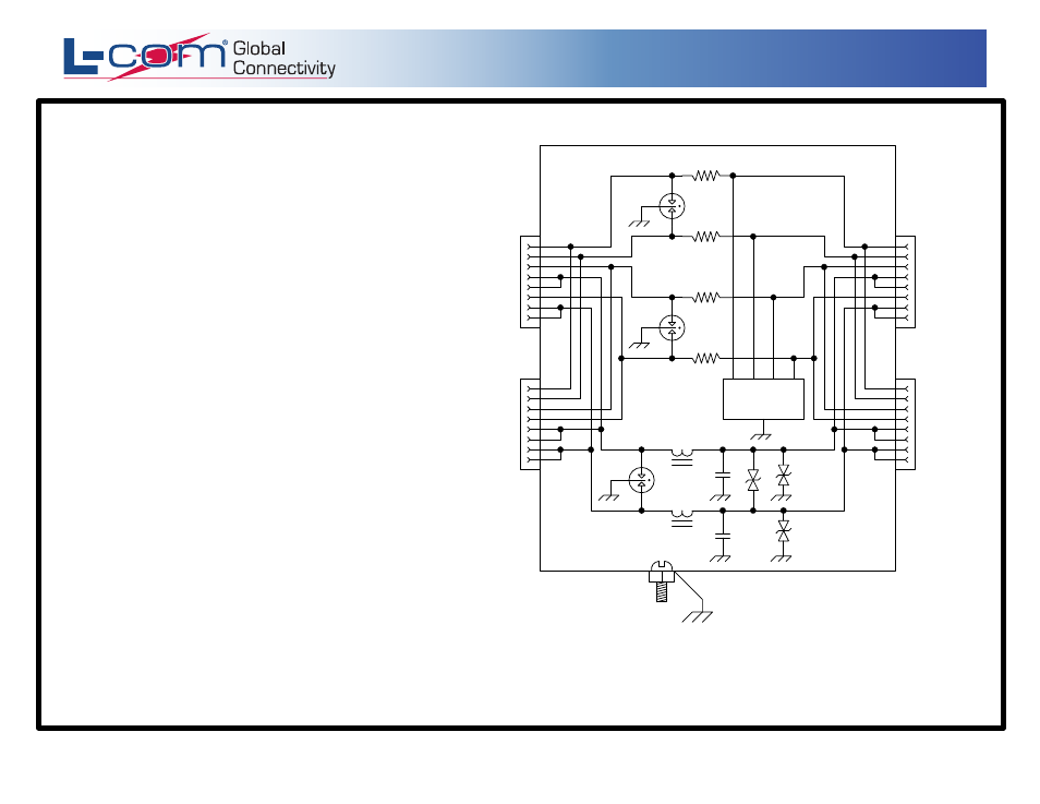
EARTH GROUND
DIODE CLAMP
ARRAY
EQUIPMENT
SIDE
LINE SIDE
R
R
R
R
GT
GT
GT
L
L
RJ-45
TERMINAL
STRIP
RJ-45
TERMINAL
STRIP
1
2
3
4
5
6
7
8
1
2
3
4
5
6
7
8
1
2
3
4
5
6
7
8
1
2
3
4
5
6
7
8
Application Note
:
This unit will not work with Cisco
®
Power Over Ethernet Injectors.
We recommend HyperLink Technologies' Cisco
®
compatible
BT-CAT5-P1R DC Injector.
AL-CAT5HPW Installation Instructions
1. Position the suppressor with the strain reliefs down
when mounting.
2. The data cable can be connected to the suppressor
via the RJ45 jacks or terminal strips.
For use with Terminal Strip: Install the data cable
through the strain reliefs, strip back cable jackets as
needed and terminate the data wires to the screw down
terminal blocks (Pinouts located next to terminal strip).
Terminal strips can be removed to ease wiring.
For use with RJ45 jacks: Install the data cable through
the strain reliefs and then terminate with RJ45 connectors.
Pinouts for jacks are as follows:
CAT5 Pinout:
1 - Data 1 +
2 - Data 1 -
3 - Data 2 +
6 - Data 2 -
4 - DC 1
5 - DC 1
7 - DC 2
8 - DC 2
3. Adjust the cable inside the of the unit to ensure proper closing
of cover, then secure by tightening strain reliefs onto cables.
4. Attach cover using the provided hardware.
5. To ensure proper operation of suppressor,
install an earth ground to the external ground
lug on the unit.
www.L-com.com
Copyright © This drawing is property of L-com Global Connectivity. All rights reserved.
L-COM, INC. 45 BEECHWOOD DRIVE NORTH ANDOVER, MA 01845
WWW.L-COM.COM E-MAIL: [email protected] PHONE: 1-800-343-1455 FAX: 1-978-689-9484
© L-com, Inc. All Rights Reserved. L-com Global Connectivity and the L-com logo are registered marks.