Peration and, Ervice e – Laurel Metal 399-D Diaper Vender User Manual
Page 2
O
PERATION AND
S
ERVICE
E
LECTRONIC
R
EQUIREMENTS
24 Volt AC
The power connection for the machine is on the circuit
board. The terminal block for incoming power is locat-
ed on the lower left corner of the Circuit Board. You
will have to lift up the Cover/Instruction sheet to locate
this terminal block, which is black in color.
BE CERTAIN TO SUPPLY 24 VOLTS/AC
T
RANSFORMER
P
OWER
R
EQUIREMENTS
The minimum power required for each vender is 1/2
amp (500mA). To run multiple venders on a transformer
first determine the total amperage required, taking into
account future additions. To determine the amperage
output of a 24 volt transformer that is given in VA, divide
the VA output by 24. For example, a 100 VA transformer
would provide 4.2 amps (100÷24) of 24 volts AC power.
This would be ample power for 8 venders.
I
NSTALLATION
The vender can be mounted on any vertical surface
without removing any part of the unit. Any standard
fastener not larger than 3/8” diameter such as wood
screws, expansion bolts, machine bolts or carriage
bolts can be used depending on the type of wall. The
vender weighs 45 lbs. empty.
The top two fasteners should be loosely installed in
the wall with the heads of the fasteners projecting out
approximately 1/4” from the wall. Raise the top shelf
of the magazine into its vend position to expose one
of the two top mounting holes in the back of the
cabinet. The keyhole shape of the mounting holes will
permit you to hang the cabinet on the two fasteners.
While in this unsecured position, mark the bottom two
mounting holes on the wall to accurately align the
lower fasteners, if necessary remove the cabinet.
Install the bottom fasteners to secure the cabinet.
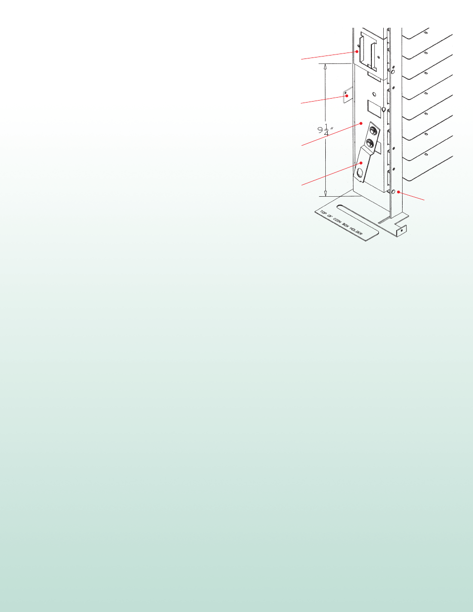
Shelf Actuator
399-A90
See Step #3
Trip Bar
2100-3
Actuating Arm
2100-12
Magazine
Assembly
399-D1
R
ETRO
F
IT
K
IT
I
NSTRUCTIONS
You do not need to take down your mounted cabinet.
Also, the Magazine Assembly can stay mounted inside
the Cabinet.
1. Remove existing Door and Security Frame from the Cabinet.
Assemble new Door on existing Cabinet and replace the
Security Frame from your old Door.
2. Remove 3 screws holding mechanical Coin Mechanism.
Loosely reinstall these 3 screws. Now remove existing Empty
Lock Rod, which is hanging down the left side of the
Magazine Assembly. This Rod will not be needed.
3. Detach Spring from side of Magazine Assembly – this is not
needed in new electronic system.
4. Shelf Actuator has double faced tape applied to it, you need
to peel back the top layer to expose the adhesive. Now apply
the Actuator on to the Trip Bar at the dimension indicated in
the diagram – (9
1
⁄
4
” from the top of the Coin Box Holder to
the bottom of the Actuator)
5. Drill
1
⁄
4
”–
1
⁄
2
” hole in back of Cabinet to be used for bringing
the power cord in.
Leave ample extra wire.
6. Mount electronic Coin Mechanism over the 3 screws you
loosely installed in Step #2 and tighten screws. The keyhole
shape of the holes in the Coin Mechanism front flange allow
you to remove and install the Coin Mechanism without taking
the screws out.
IMPORTANT – when installing the new Coin Mechanism
the round cam of the Vend Motor must go inside of the
Shelf Actuator’s flanges.
7. To install new Empty Rod it is recommended to first insert
bottom of Rod through the guide hole at the top of the
Coin Mechanism (above the Empty Switch). Now insert
top of Rod as before (identical to mechanical system).
Before resetting the shelves lift rod up to see if it falls
freely and trips the Empty Switch.
2
7