Laurel Electronics LT SERIES TRANSMITTERS PULSE INPUTS User Manual
Page 17
-
- 17 -
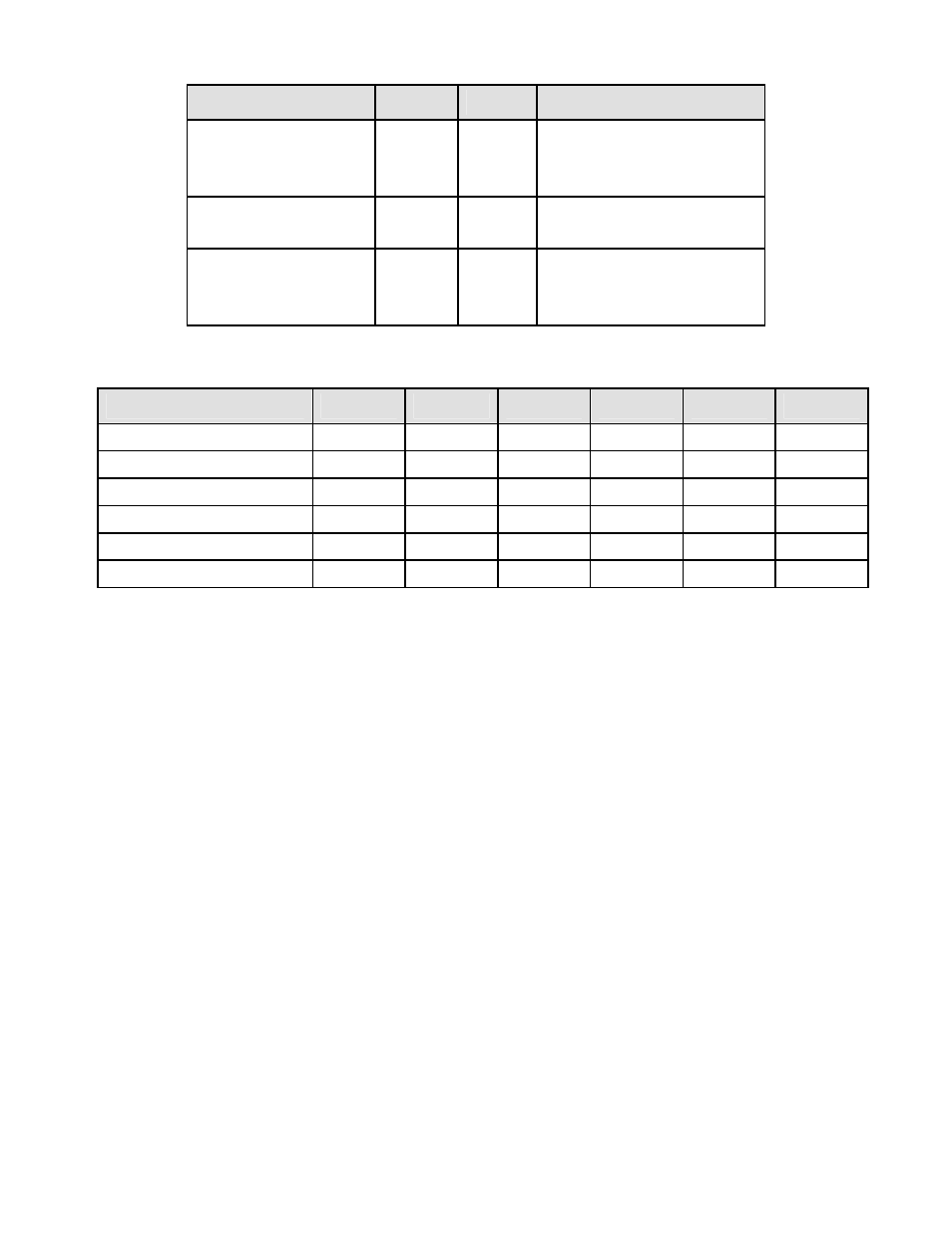
Function
Block
Jumper Setting
Frequency Response A0 & B0 -
b
a
1 MHz max
30 kHz max
250 Hz max
Bias Resistor
A1 & B1 a
b
10 kOhm pull-up to 5V
10 kOhm pull-down to -5V
Contact Debounce
A4 & B4 b
a, c
c
None
3 msec
50 msec
Common Jumper Settings
Input Type
Vmax
A0 & B0
A1 & B1
A2 & B2
A3 & B3
A4 & B4
Logic levels
250V
-
-
-
a
b
NPN open collector
NA
b
a
-
a
b
PNP open collector
NA
b
b
-
b
b
Contact closures
NA
a or b
a
-
a
a, c
Line frequency
250V
b
-
-
-
a, c
Turbine flow meter
250V
b
-
a
-
b
RATE & FREQUENCY MODES
Frequency in Hz is determined by timing an integral number of pulses over a user-specified
Gate Time from 0 to 199.99 sec and taking the inverse of average period. The typical internal
display update rate is Gate Time + 1 period + 30 ms. Selecting a longer Gate Time produces a
more stable reading as more cycles are averaged, but slows down the update rate. At very low
frequencies, the update rate is controlled by the period. A Time Out from 0 to 199.99 sec is also
selectable. This is the time the transmitter waits for a signal to start or end a conversion. If the
signal is not received before the Time Out ends, the transmitter reads zero. The longer the Time
Out, the lower the minimum frequency that can be processed.
Rate in engineering units can be obtained by applying a scale factor to frequency, or by using
the Coordinates of 2 Points method, where two inputs in Hz and the corresponding desired two
internal readings are entered directly.
• Rate A, B determines rate independently for Channel A (Item #1) and Channel B (Item #2).
Either item can be selected for the analog output.
• Rate A Only determines rate only for Channel A. Channel B is not used.
• Rate A, A Total (Extended counter) determines Rate for Channel A (Item #1) and Total for
Channel A (Item #2) since last reset. Total can count down from an offset by entering a
negative scale factor. Only used for non-linear inputs.