Laurel Electronics QLS Quad Output 4-20 mA Current Loop - Datasheet User Manual
Page 3
LAUREL
ELECTRONICS INC., 3183-G Airway Ave., Costa Mesa, CA 92626, USA • Tel 714-434-6131 • www.laurels.com 3
QLS Theory of Operation
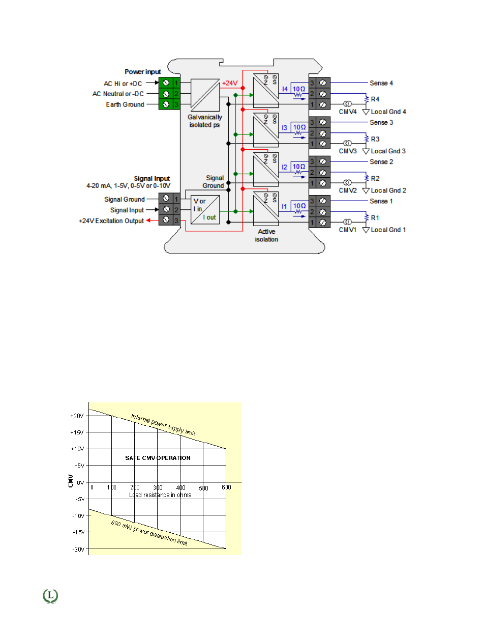
Galvanic & Active Isolation: A single input current loop is split into four independent output loops I1, I2, I3
and I4 by four current generators. The input and output signals are galvanically isolated from power and earth
ground by up to 275 Vac. Active circuitry isolates the input Signal Ground and the four output Local Grounds
from each other to a common mode voltage of ±10V, thereby avoiding ground loops. Common mode volt-
ages, labeled CMV1 to CMV4 in the diagram, reflect actual voltage differences between Signal Ground and
Local Ground. Such differences can be caused by current flows in the factory.
Floating loads: Any output load R that is floating (not connected to Earth Ground or a Local Ground) can be
connected between current output (Pin 1) and current return (Pin 2). Current return is internally tied to Signal
Ground, which can be floating or be connected to earth ground.
Grounded loads: Any output load R can be connected to a Local Ground instead of current return. The Local
Grounds can each be different, but can only differ from Signal Ground by a safe common mode voltage CMV.
Signal Ground should be tied to Earth Ground to minimize noise pickup.
QLS Safe Operation
Common mode voltage: If a load R is grounded to
a Local Ground, the available common mode voltage
CMV is limited on the positive side by the unit's inter-
nal power supply and on the negative side by the 600
mW power dissipation limit of an output transistor.
The diagram shows allowable CMV as a function of
output load resistance R. For example, with a 250Ω
load, CMV can range from -13V to +17V. With a 500Ω
load, CMV can range from -18V to +12V. The unit will
not work correctly if CMV limits are exceeded or load
resistance is greater than 600Ω.