Block diagram – Ampro Corporation Single Board Computer Littleboard 550 User Manual
Page 16
Chapter 2
Product Overview
10
Reference Manual
LittleBoard 550
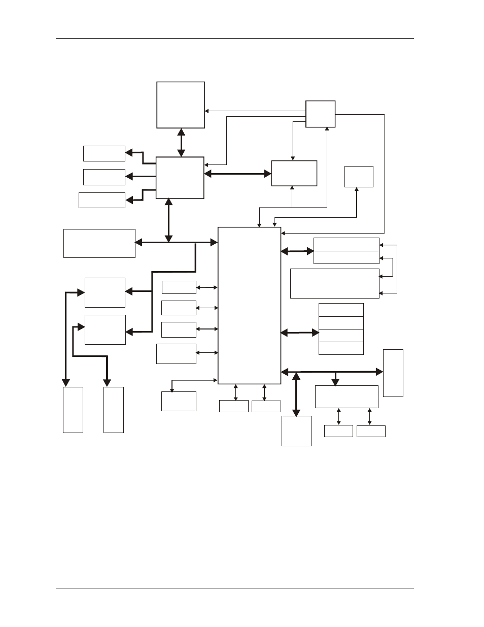
Block Diagram
Figure 2-3 shows the functional components of the board.
L
B
550B
lkD
iag
m
VIA EDEN
CPU
™
SDRAM
SODIMM
Southbridge
VT82C686B
Memory Bus
Ethernet
Controller
82251ER
M
a
gne
ti
cs-
R
J
4
5
Keyboard/
Mouse
SMBus
Northbridge
VT8606
PC104-Plus
Bus Connector
PCI Bus
IrDA 1.1
Floppy
AC’97
CODEC
COM3
COM4
IDE Primary
IDE Secondary
USB Port 4
USB Port 3
USB Port 2
USB Port 1
USB
ATA
PC
1
0
4
Co
n
n
ec
to
r
Super I/O
Dual Serial Port
COM1
COM2
ISA Bus
AC’97 Link
Clock
Temp
512kB
ROM
BIOS
IDE Devices,
(HDDs, CompactFlash,
CD-ROM, etc.)
Ethernet
Controller
82251ER
CRT VGA
TFT LCD
LVDS LCD
M
a
gnet
ics-
R
J
4
5
Parallel
Figure 2-2. LittleBoard 550 Functional Block Diagram