American Access Systems RemotePro KP 12-000sg User Manual
Page 6
Page 6 American Access Systems / Security Brands, Inc.
the IDLe moDe
The idle mode is the mode of operation in which the unit sits and waits for data from the keypad. When a key is
pressed you will have approximately 3 seconds between keypresses before the unit resets.
the LeD’s
The yellow/green LED serves as a ready indicator and stays lit while the REMOTE PRO is waiting for data from the
keypad. When a key is pressed the yellow/green led will go out until either 5 numeric keys are pressed on the
keypad or a time of 3 seconds is exceeded between keypresses.
the * AnD # KeYs
The * and # keys both serve as clear keys and should be used if an entry error is made. A double beep will be heard
from the unit when either key is pressed.
enteRIng DAtA
A beep will be heard from the unit when a numeric key is pressed. You may enter any 5 digit code from the keypad
from 00000 to 65534. After a code has been entered the unit transmits two codes, a facility or site code and the
numeric code entered from the keypad. The facility or site code is programmed via the dip switches on the board
(See page 4.) If a number greater than 65534 is entered, the unit will error internally and data will not be transmitted
from the unit.
the DIP sWItChes
The Remote Pro line incorporates a facility or site code programmable from 0 to 255 via the dip switches on the circuit
board. When a code is entered from the keypad, 2 different codes are transmitted from the Remote Pro. The facility
code, and the keypad code itself. The facility code can therefore be used to identify which keyad is sending the
code in a multiple door layout. The facility code allows up to 256 different units to be uniquely identified in a system.
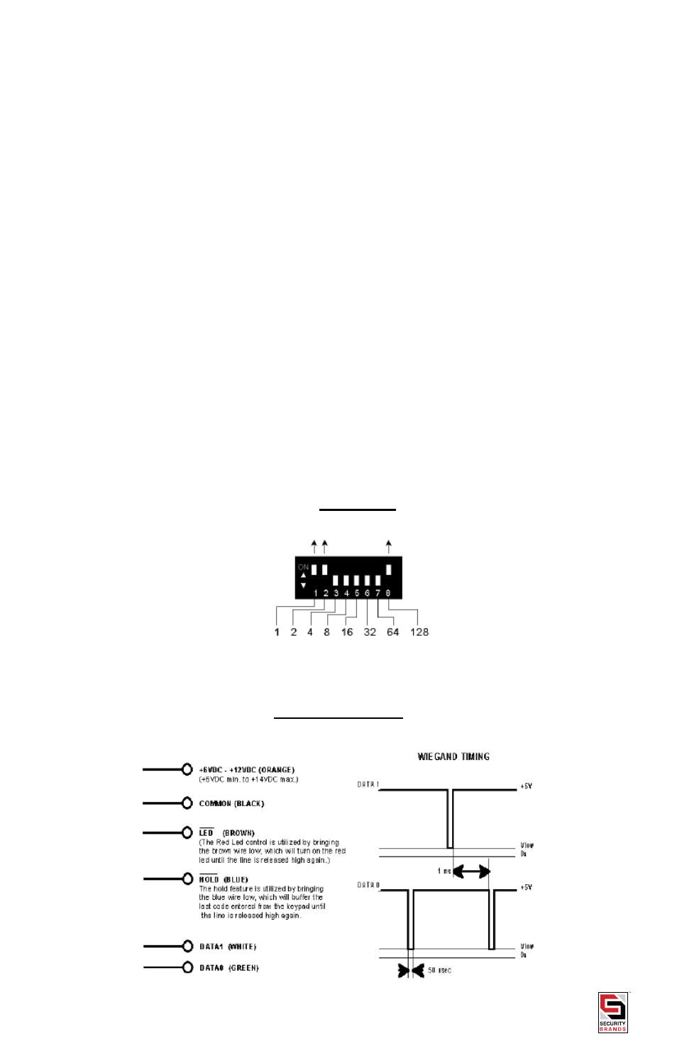
Each dip switch corresponds to a specific number.Switch 1 = “1”, 2=”2”, 3=”4”..... 8=”128”. The facility code is set by
turning dip switches on and then adding their values together. For example, if you wished to set the facility code to
“131”, you would set dipswiches 1,2, and 8 to on.
EXAMPLE
“1” + “2” + “128” = 131
TIMING SIGNALS