Optional postal lock, Optional remote keypad, Postal lock installation – Controlled Products Systems Group AE-500 User Manual
Page 12
12
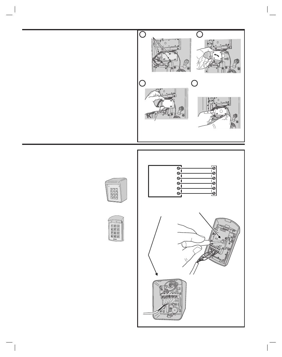
Optional Postal Lock
A postal lock can be installed in the AE-500 Entry System to provide keyed
access for the postal service. The AE-500 case is designed to accept a
U.S. Postal Service postal lock. When the postal lock is engaged, Relay
Channel “A” will activate.
Postal Lock Installation
1. Remove the four locknuts that retain the postal lock switch plate
(above the keypad on the AE-500 faceplate).
2. Remove the switch plate from the four studs.
3. Install the postal lock assembly onto the four studs. The postal
lock’s moving plunger should point towards the cabinet hinge (see
fi gure).
4. Replace the postal lock switch plate with the microswitch oriented
inward where it will be pressed by the postal lock’s moving plunger
(see fi gure).
5. Secure the postal lock and switch plate with the four locknuts.
✦ NOTE: Be sure the postal lock’s plunger actuates the
microswitch. Adjust the switch plate and the postal lock then test
the action until the microswitch fully actuates.
6. Tighten the four locknuts after the adjustment and testing is
complete.
Optional Remote Keypad
A remote keypad can be connected to the AE-500. A typical application
for a remote keypad would be to control a second door or gate.
Two models of keypads are available to connect to the AE-500. One
keypad can be used at a time with each AE-500 unit.
AM-KP Exterior Keypad
The Model AM-KP is housed in a rugged
cast aluminum enclosure designed for
exterior installations. The keypad can be
mounted to a pedestal or directly to a wall. A
keylock secures the keypad to the mounting
backplate.
AM-KPI Interior Keypad
The Model AM-KPI keypad is designed to
be mounted indoors in a standard single-
gang electrical box. Tamper resistant screws
secure the keypad to its mounting plate.
The die-cast keys are illuminated with white
LEDs. The keypad is supplied with a satin-
chrome bezel and three interchangeable
colored bezels (white, ivory, & bronze) to
customize the keypad appearance for the
installation.
1. Mount and install the keypad as described in its installation
instructions.
2. Route 6-conductor cable from the AE-500 to the keypad.
• For wire runs up to 300 feet use 24 AWG Belden Type 9931 or
equivalent.
• For wire runs up to 600 feet use 20 AWG Weico Type 9405 or
equivalent.
3. Set
the
DEVICE ADDRESS rotary switch in the keypad to address
number one.
4. Connect the 6-conductor cable to the keypad and the AE-500
KEYPAD terminals as shown in the fi gure.
*
5
6
7
8
9
0
#
1
2
3
4
AM-KP
AM-KPI
REMOTE
KEYPAD
PWR
GND
DAT1
DAT0
DVAL
PCLK
DVAL
DAT0
DAT1
GND
PWR
PCLK
KEYPAD
TERMINALS
SET THE REMOTE
DEVICE ADDRESS TO 1
AM-KPI
REMOTE
KEYPAD
AM-KP
REMOTE
KEYPAD
REMOVE LOCKNUTS
REMOVE PLATE
INSTALL POSTAL LOCK
PLUNGER POINTS TO
CABINET HINGE
REPLACE PLATE WITH THE
MICROSWITCH TOWARDS
THE FRONT OF THE CABINET,
REPLACE LOCKNUTS
NOTE: BE SURE THE POSTAL LOCK'S PLUNGER ACTUATES THE
MICROSWITCH. ADJUST THE SWITCH PLATE AND THE POSTAL LOCK
THEN TEST THE ACTION UNTIL THE MICROSWITCH FULLY ACTUATES
4
3
2
1