Comprehensive CVG-724xl User Manual
Page 12
8
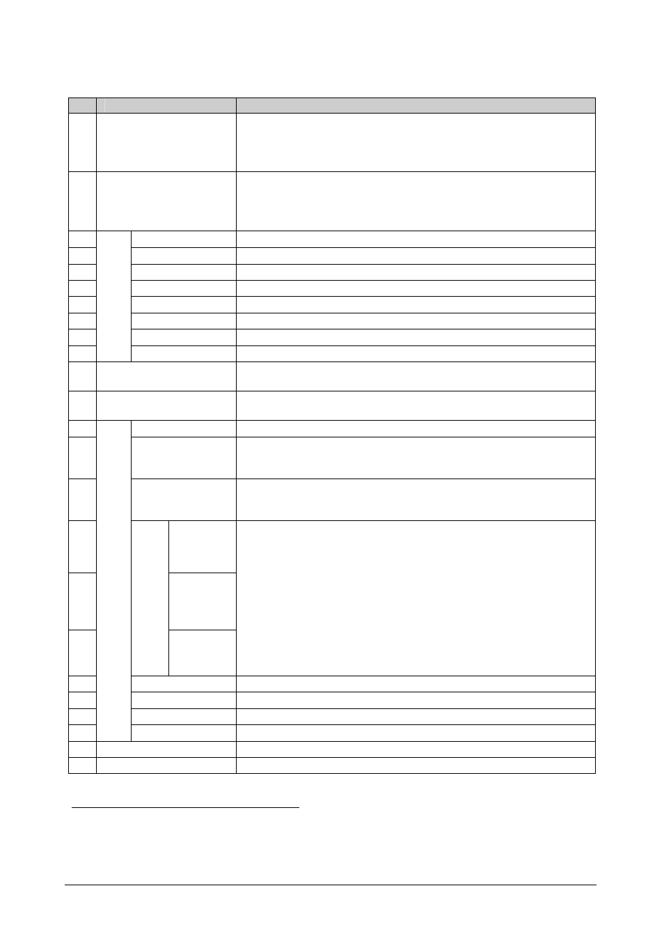
Table 2: Rear Panel Presentation Switcher / Scaler Features
#
Feature
Function
1 VIDEO OUT 1
HD15 Connector
Connects to the video acceptor (for example, a plasma display, projector or
monitor) that displays the scaled output
In the default HDTV mode, the signal goes out via 3 PINS: PIN 1 is P
r
, PIN 2
is Y, PIN 3 is P
b
2 VIDEO OUT 2
HD15 Connector
Connects to the video acceptor (for example, a plasma display, projector or
monitor) that displays the scaled output
In the default HDTV mode, the signal goes out via 3 PINS: PIN 1 is P
r
, PIN 2
is Y, PIN 3 P
b
3
AV1
Connects to the stereo audio input from composite video source 1
4
AV2
Connects to the stereo audio input from composite video source 2
5
YC1
Connects to the stereo audio input from s-Video source 1
6
YC2
Connects to the stereo audio input from s-Video source 2
7
COMP
Connects to the stereo audio input from the component video source
8
DVI
Connects to the stereo audio input from the DVI graphics source
9
VGA
1
1
Connects to the stereo audio input from the VGA graphics source 1
10
A
U
D
IO
IN
T
er
m
in
al
B
lo
ck
C
on
ne
ct
or
s
VGA
1
2
Connects to the stereo audio input from the VGA graphics source 2
11 LINE AUDIO OUT Terminal
Block Connector
Connects to the stereo audio acceptor
12 SPKR OUT
Terminal Block Connector
Connects to the speakers
13
DVI Connector
Connects to the DVI (digital video interface) graphics source
14
VGA
1
1 HD15
Connector
Connects to the VGA (analog interface) graphics source 1. When
connecting an HDTV source, the signal goes in via 3 PINS: PIN 1 is Y, PIN
2 is Pb, and PIN 3 is Pr
15
VGA
1
2 HD15
Connector
Connects to the VGA (analog interface) graphics source 2. When
connecting an HDTV source, the signal goes in via 3 PINS: PIN 1 is Y, PIN
2 is Pb, and PIN 3 is Pr
16
Y RCA
Connector
17
Pb/Cb RCA
Connector
18
C
O
M
P
O
N
E
N
T
Pr/Cr RCA
Connector
Connect to the component (Y, Pb/Cb, Pr/Cr) or RGB video source. If RGB
colorspace is used, connect as follows:
For video frequencies
2
, connect:
Green to the Y connector
Blue to the Pb/Cb connector
Red to the Pr/Cr connector
For Graphics frequencies
3
, connect:
Red to the Y connector
Green to the Pb/Cb connector
Blue to the Pr/Cr connector
19
YC2 4p Connector
Connects to the s-Video source 2
20
AV2 RCA Connector Connects to the composite video source 2
21
YC1 4p Connector
Connects to the s-Video source 1
22
V
ID
E
O
IN
P
U
TS
AV1 RCA Connector Connects to the composite video source 1
23 RS-232 DB 9 Connector
Connects to PC or Serial Controller
24 Power Connector with Fuse AC connector enabling power supply to the unit
1 Only the CVG-724xl has 2 VGA connectors. The CVG-719xl and CVG-720xl have 1 VGA connector
2 50Hz or 60Hz interlaced video
3 Including HD (480p, 576p, 720p and 1080i)