CNB D1811PVF User Manual
Dome camera color dome, Sdnr, Axis
•
5
5
0
T
V
L
i n
e s
•Supe
r D
ig
ita
l N
ois
e R
edu
ctio
n
SDNR
SDNR
1/3" SONY CCD
Design and specifications are
subject to change without notice.
Dome Camera
Color Dome
Vandal Proof
Digital DSP
LENS
.Vari-focal
.Fixed Lens
•
S
im
p
l e
t
o i
n s t a l l
3 -
A
x
i s
b
r
a
c
k
e
t
m
ak
es
ad
ju
st
m
en
t
e
a
s
y
.
Super
D i g i t a l
N o i s e
Reduction
Super
D i g i t a l
N o i s e
Reduction
3-Axis
Digital Slow Shutter
DSS
NAME AND FUNCTION:
COMPOSITION:
PRECAUTIONS:
Model
Signal System
Scanning System
Scanning Frequency (H)
Scanning Frequency (V)
Image Sensor
Total / Effective Pixels No.
S / N Ratio
Resolution
Video Output Level
Lens
Focus
Sync. System
Sensitivity (F1.2)
Electronic Shutter
White Balance
BLC / FL
DSS
DNR / AGC / D&N
Input / Output Connector
Operrating Temperature
Storage Temperature
Power Consumption
(Option : AC 24V/DC 12V)
Dome Size (Ø)
NTSC PAL
NTSC : 525 Lines PAL : 625 Lines
2 : 1 Interlace
15.734kHz 15.625kHz
59.94Hz 50Hz
1/3 inch SONY IT CCD
410K 470K
50dB Min. (AGC Off)
550 TV Lines
1.0 Vp-p (75 Ohms, composite)
Fixed Lens (f=3.8mm, 4mm Selectable)/ Vari-focal Lens
Manual
Internal
0.3 Lux (color)/ 0.1 Lux (B/W) / 0.008 Lux (DSS On, x32)
1/60 ~ 120,000 Sec. 1 /50 ~ 120,000 Sec.
Auto
On / Off Selectable
Max 32 times
AUTO
Power, Video
-10°C ~ 45°C
-20°C ~ 65°C
DC 12V (DC 9.6V~13.2V) / 150mA (Max)
AC 24V (20V~28V) or DC 12V (10V~15V), 3W (Max)
85mm
CAMERA SET-UP:
Vari-focal Lens Type
P
/N
:3
8
1
0
-0
0
9
6
A
ve
r.
0
6
1
2
E
Service Monitor Connecter:
Use service monitor connector
to set camera angle & focus
when installing.
a
Function Selection Switch:
•BLC(Back Light Compensation)
ON/OFF
•DSS(Digital Slow Shutter) ON/OFF
•FL(Flickerless) ON/OFF
Bright Level Adjustment V.R
c
b
The image does not
appear on the screen.
Check the power source for the monitor and camera
and assure that the voltage and polarity are properly
connected and being supplied correctly.
The image on the
screen is dim.
Check if the lens is stained. If dirty, clean the lens with
a soft, clean cloth.
Adjust the Back Focus of the lens again.
The camera does not work
properly, the surface of the
camera case is hot, and a black
line appears on the screen.
Check if you have connected the camera to a proper
power source and If there is no problem with the power,
turn the unit off immediately and seek assistance from
our After Service department.
The screen blinks a lot.
Check if the camera is pointed toward the sun or a
fluorescent lamp.
Adjust the angle or location of the camera if too much
light is coming into the screen.
TROUBLESHOOTING:
If you have trouble operating your camera, refer to the following.
If the guidelines do not enable you to solve the problem, contact an authorized technician.
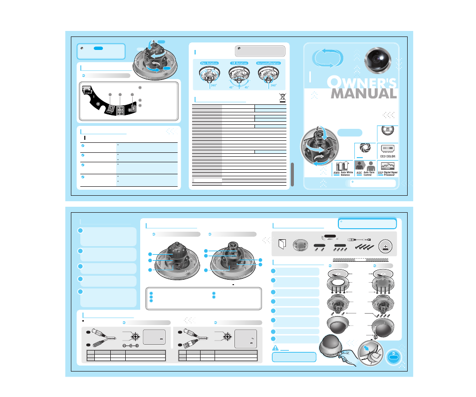
Camera Lay-out
Tilt rotation: Adjusting the vertical angle.
Pan rotation: Adjusting the horizontal angle.
Horizontal rotation:
Adjusting the horizontal position of the screen.
Focus handle: Focus (Far or Near)
Zoom handle: Zoom (Tele or Wide)
1
2
3
4
5
SPECIFICATIONS:
Simple to install
3-Axis bracket makes
adjustment easy.
The 3D bracket (Pan, Tilt and Horizontal)
allows the camera to be manually as well
as moved horizontally and vertically.
360º
360º
90º
Fixed Lens Type
1
3
2
Vari-focal Lens Type
4
5
2
1
3
2.
DS
S
ON
3
.F
L
OF
F
1.
BL
C
OF
F
ON
3
1 2
BR
IG
HT
VIDEO
c
a
b
!
Do not install the camera in
extreme temperature conditions.
Do use the camera under conditions where
temperatures are within -10°C to 45°C.
Be especially careful with ventilation
under high temperatures.
!
Do not install or use the camera
in an environment where the
humidity is high.
It can cause the image quality to be poor.
!
Do not drop the camera or
subject them to physical shocks.
It can cause malfunctions to occur.
!
Do not disassemble the camera.
There are no user-serviceable parts
inside it.
!
Note
When this camera is installed near
wireless communication devices
that emits strong electromagnetic
field, irregularity such as noise on
the monitor may appear.
Connecting to
Monitor and Power
AC 24V/DC 12V Power Type
AC 24V/DC 12V Power Type
CONNECTION:
No.
#1
#2
Function
Video Output
Power Input
Remark
1.0 Vp-p
DC 12V(DC9.6V~13.2V), 150mA(Max)
Terminal Color
Yellow
Red
No.
#1
#2
Function
Video Output
Power Input
Remark
1.0 Vp-p
AC24V(20V~28V)orDC12V(10V~15V), 3W(Max)
Terminal Color
Yellow
Green
Video
(Yellow)
Power - DC 12V
(Red)
#1
#2
#1
#2
Video
(Yellow)
Power - AC 24V/ DC 12V
(Green)
Video Output
GND
Video Output
GND
• The wire is
polarized.
• The wire is
non-polarized.
• Use AC 24V
power source
or DC 12V
power source.
• Use DC 12V
power source.
You must be fully aware of all the distinctive
features and precautions related to this
camera before installing it.
INSTALLATION:
Draw out power / video wires
to the connecting places.
4
Fix the surface mount bracket
by screws on the ceiling.
3
Stick the guide pattern on the
wall or ceiling.
1
Adjust desired focus and scene
by turning and moving the
3-axis camera bracket by hand.
6
Drill four holes according to
the guide pattern then insert
anchors into the drilled holes.
2
Put the dome cover over the base.
7
Fix the dome cover on the base
by covering.
8
Connect the dome base to the
surface mount bracket by screws.
5
Insert coin to the side hole and
remove the dome cover by twist coin.
NOTE
Ceiling
Guide Pattern
Surface Mount
Bracket
Surface Mount
Screw
Screw
Dome Base
Dome Cover
L-Wrench
A Type
B Type
Built-in camera bracket
will make user much easier to
rotate in any direction.
3-axis
A Type
Owner's Manual
Guide Pattern
Service Monitor Cable
Surface Mount Bracket
Surface Mount Screw
L-Wrench
※
B Type
Screw
※
B Type
Screw
※
A Type