Sensor device – CNB IVP4000VR User Manual
Page 8
X
X
N
N
E
E
T
T
N
N
e
e
t
t
w
w
o
o
r
r
k
k
D
D
o
o
m
m
e
e
C
C
a
a
m
m
e
e
r
r
a
a
I
I
n
n
s
s
t
t
a
a
l
l
l
l
a
a
t
t
i
i
o
o
n
n
M
M
a
a
n
n
u
u
a
a
l
l
8 / 17
Network Terminal
This Ethernet terminal connects to 100Mbps LAN through an RJ-45 connector. When optional PoE is used,
the power will be supplied from the Network Cable.
Link LED
Yellow light indicates that the network is properly connected.
Act LED
Green light indicates that the XNET system connected to 100Mbps LAN. This green lamp will blink if
the system receives data.
2
2
.
.
3
3
.
.
3
3
C
C
o
o
n
n
n
n
e
e
c
c
t
t
i
i
n
n
g
g
t
t
o
o
A
A
l
l
a
a
r
r
m
m
D
D
e
e
v
v
i
i
c
c
e
e
s
s
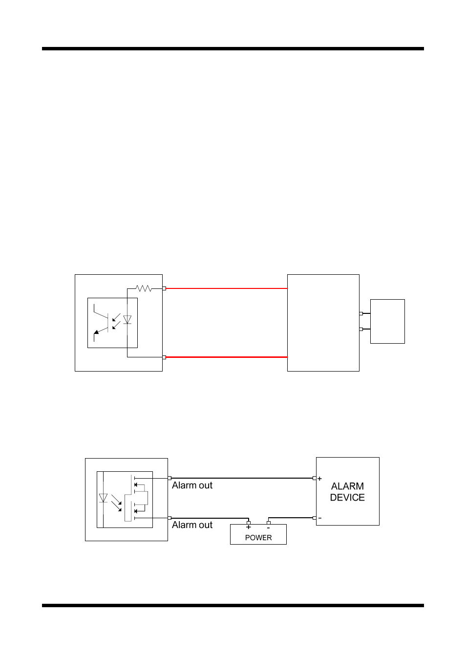
Alarm Input
Wires from various sensor type (IR, heat, and magnetic) can be connected to
Alarm
in(+)/(-) terminal as
shown in figure 2.5. (NC or NO of sensor input can be selected at Menu screen.)
Alarm Sensor device requires a separate power source.
Alarm in(+)
Alarm in(-)
Photo Coupler
Sensor
Device
Signal(+5 ~ 30VDC)
GND
Adaptor
+
-
Internal Circuitry External Circuitry
Alarm Output
This terminal can only be connected up to AC 30V/400mA or DC 30V/400mA. An additional relay
device has to be used to control higher voltage or current.
Internal Circuitry External Circuitry