CNB NGE2055F User Manual
Page 8
8 / 17
XNET Network Box Camera Installation Manual
LINK : Yellow light indicates that he network is properly connected.
ACT : Green light indicates that the XNET system connected to 100Mbps LAN. This green lamp will
blink if the system receives data.
STATUS LED : Indicates the operation status
EVENT LED : Green light indicates that Alarm Out signal is turned on.
POWER LED : Red light indicates that 12V DC power or 24V AC power is connected.
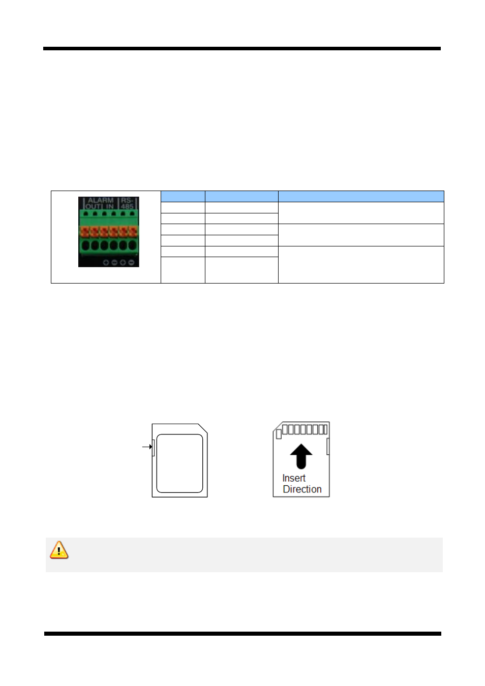
RS-485 and ALARM In/Output Terminal
Pin
Description
Set up
1
Alarm Out(+)
Select NC/NO at menu screen
2
Alarm Out(-)
3
Alarm In(+)
Select NC/NO at menu screen
4
Alarm In(-)
5
RS485 +
6
RS485 -
RS-485: When properly connected, you can remotely control Pan/Tilt device with RS-485 control
interface.
Alarm In: This connects to an Alarm Sensor signal. Only one sensor can be connected.
Alarm Out: This connects to an external Alarm device that operates by a relay such as Siren
Lamp or Alarm Light. Only one Alarm device can be connected.
SD CARD SLOT : Enables recording of video data to an external memory device upon occurrence of an
event. Please use less than 32 GB SD Memory.
Labeling
position
Write-protect
tab
Figure 2-4. SD CARD
Power Terminal: Connect Power to this terminal.(DC12V, AC24V)
Do not use the other power connector when powering up the product through PoE.
The product is not covered under warranty when it is damaged by connecting both
Ethernet power and 12V DC power(or 24V AC power) to this terminal.
1 6