Locked brake, Maintenance/inspection, Figure 2 – CM-ET Series 603 User Manual
Page 4: Figure 4 figure 3, Figure 5
LOCKED BRAKE
If a hoist under load is suddenly relieved of the load by removing the load from the hoist by some other
means, the brake will remain locked. The brake could also lock if the lower hook block is run tightly
against the frame. To unlock the brake, move the directional lever to the (
) UNLOAD position and pull
sharply on the handle, or reapply the load and operate the hoist in the normal manner.
MAINTENANCE/INSPECTION
The Series 602/603 Lever Hoist normally requires very little maintenance, other than the frequent and
periodic inspection listed in the chart on page 5. However, if the hoist is disassembled for inspection,
the following should be observed when reassembling.
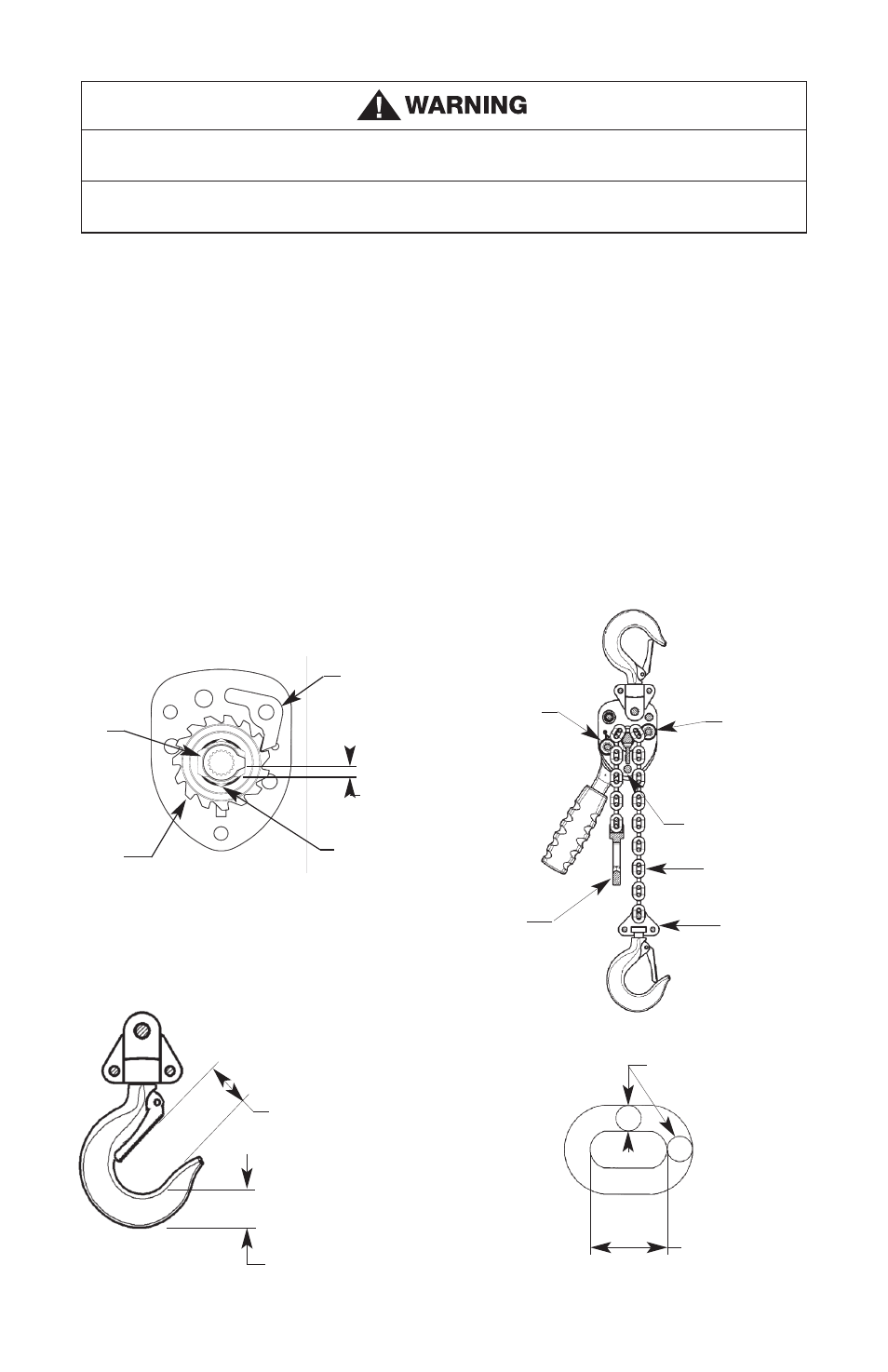
1. The pawl must engage the teeth of the ratchet as shown in Figure 2.
2. The check washer must be positioned on the ratchet hub as shown in Figure 2.
3. When installing the chain, it must be fed through the chain guide rollers with the welds away
from the liftwheel, the lower hook must be directly below the upper hook and the loose end ring
must be positioned and oriented at the end of the chain as shown in Figure 3
4. A rivet is used to attach the latch to the hook. To remove the latch grind off the head of the rivet.
When installing the latch, only peen over the end of the rivet enough to secure it.
If directional lever is forced out of engagement with a load applied, load will be released.
PAWL
1
/8"
RATCHET
PAWL
RATCHET
CHECK
WASHER
FIGURE 2
CHAIN GUIDE
ROLLER
CHAIN GUIDE
ROLLER
STRIPPER
LOAD CHAIN
WELDS AWAY
FROM LIFTWHEEL
LOWER HOOK
BLOCK
LOOSE END RING-
POSITION AS SHOWN
0.91" (23.1 mm)
MAXIMUM
THROAT OPENING
.71" (18mm)
MINIMUM SEAT
FIGURE 4
FIGURE 3
.149" (3.8mm)
STOCK DIAMETER
.496" (12.6mm)
MAXIMUM PITCH
FIGURE 5
4
Series 602/603 Operating, Maintenance & Parts Manual
TO AVOID INJURY:
With a load applied to the hoist, do not force the directional lever into the center (neutral) position.