Audiovox VC-600 User Manual
Page 2
2
2
2
2
2
water to wipe off any dust, if necessary.
s Do not touch the CCD sensor. If necessary, use
a soft, lint-free cloth moistened with alcohol
to clean the CCD sensor.
s If the camera does not operate properly,
unplug the unit and contact your local
dealer.
6. Installation
6. Installation
6. Installation
6. Installation
6. Installation
s Select base to be used.
s Screw the camera to the base. If using the
wall mount, screw the base to the wall before
attaching camera.
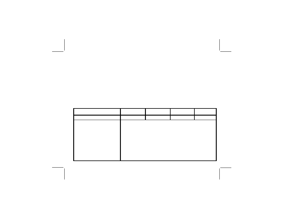
C H A N N E L
C H A N N E L
C H A N N E L
C H A N N E L
C H A N N E L
C H 1
C H 1
C H 1
C H 1
C H 1
C H 2
C H 2
C H 2
C H 2
C H 2
C H 3
C H 3
C H 3
C H 3
C H 3
C H 4
C H 4
C H 4
C H 4
C H 4
F R E Q U E N C Y
2413 MHz
2432 MHz
2451MHz
2470 MHz
O U T P U T P O W E R
10 mW
OUTPUT IMPEDANCE
50 ohms typical
P O W E R
12 VDC supplied by AC/DC adapter
C U R R E N T
260 mA
VIDEO OUTPUT
1Vp-p composite video (75 ohms)
AUDIO OUTPUT
2Vp-p max
DIMENSIONS
L:
L:
L:
L:
L: 77mm H:
H:
H:
H:
H: 56mm D:
D:
D:
D:
D: 56mm
OPERATING TEMPERATURE
-10° C to +50° C
W E I G H T
115 grams
s Carefully screw the antenna to the camera.
s Plug the AC/DC adapter into the camera Power
Jack and then into the wall.
s Set channel select switch to the corresponding
channel of the receiver.
s Adjust the camera for best viewing angle.
7. Channel Selection
7. Channel Selection
7. Channel Selection
7. Channel Selection
7. Channel Selection
After connecting and turning on the equipment,
select the channel that gives the best reception and
least interference. The channel number must match
the channel number of the receiver. The antenna
is normally positioned vertically but its angle may
be changed to obtain the best reception.
128-5680
128-5680
128-5680
128-5680
128-5680
2 of 4
2 of 4
2 of 4
2 of 4
2 of 4
8.
8.
8.
8.
8.
S
S
S
S
S
p
p
p
p
p
e
e
e
e
e
c
c
c
c
c
i
i
i
i
i
f
f
f
f
f
i
i
i
i
i
c
c
c
c
c
a
a
a
a
a
t
t
t
t
t
i
i
i
i
i
o
o
o
o
o
n
n
n
n
n
s
s
s
s
s