High-voltage barrier, Wiring for power, High-voltage barrier wiring for power – Hach-Lange POLYMETRON 9523 User Manual User Manual
Page 13
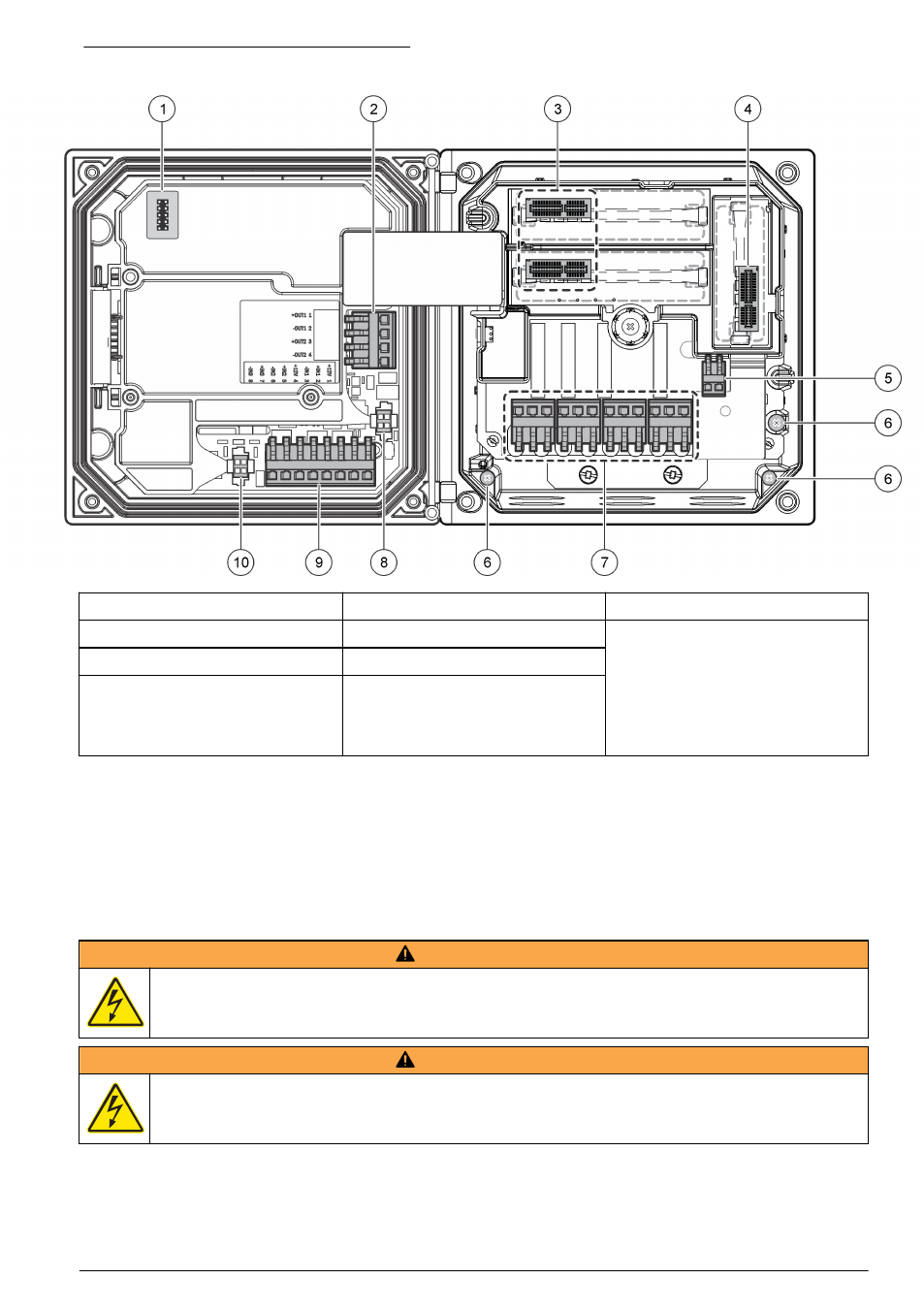
Figure 4 Wiring connections overview
1 Service cable connection
5 AC and DC power connector
1
9 Discrete input wiring connector
1
2 4-20 mA output
1
6 Ground terminals
10 Digital sensor connector
1
3 Sensor module connector
7 Relay connections
1
4 Communication module
connector (e.g., Modbus,
Profibus, HART, optional
4-20 mA module, etc.)
8 Digital sensor connector
1
1
Terminals can be removed for improved access.
High-voltage barrier
High-voltage wiring for the controller is located behind the high-voltage barrier in the controller
enclosure. The barrier must remain in place except when installing modules or when a qualified
installation technician is wiring for power, alarms, outputs or relays. Do not remove the barrier while
power is applied to the controller.
Wiring for power
W A R N I N G
Potential Electrocution Hazard. Always disconnect power to the instrument when making electrical
connections.
W A R N I N G
Potential Electrocution Hazard. If this equipment is used outdoors or in potentially wet locations, a
Ground Fault Interrupt device must be used for connecting the equipment to its mains power source.
English 11