Cashco 5500 User Manual
Page 9
9
IOM-5500
SECTION IX
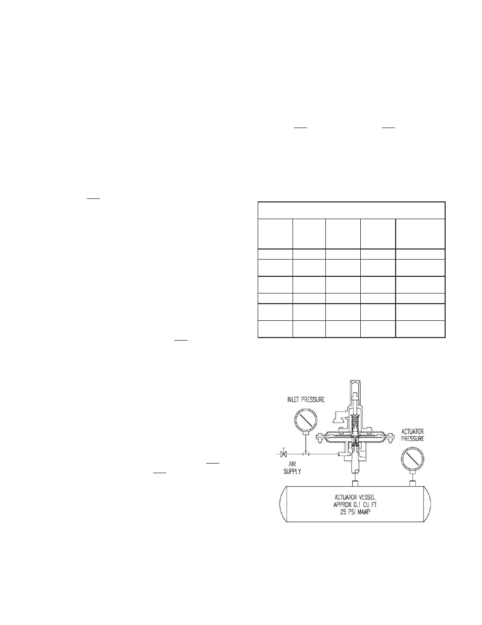
Pilot Valve Test Stand
IX. PRESSURE CALIBRATION AND
TESTING PROCEDURE FOR PILOT:
1. To determine set pressure, slowly increase
the pilot inlet pressure. Simulated actuator
pressure will rise with inlet. As set pressure
is approached, the actuator pressure will be-
gin to decrease. Continue to increase the
inlet pressure slowly until the actuator pres-
sure is 90% (+/- 10%) of the inlet pressure.
This is the set pressure.
4QVCVG VJG UGV RTGUUWTG CFLWUVKPI UETGY
() CW to increase set pressure or CCW
to decrease set pressure. Continue to rotate
VJG CFLWUVKPI UETGY CPF TGRGCV VJG VGUV RGT
5VGR RTGXKQWU WPVKN VJG URGEKſGF UGV RTGU-
sure is achieved.
3. To determine reseat pressure, slowly de-
crease the inlet pressure and the actuator
pressure will begin to increase. Reseat oc-
curs when the actuator pressure equal the
inlet pressure.
4. The difference between set and reseat
RTGUUWTGŒDNQYFQYPŒ ECP DG CFLWUVGF YKVJ
the blowdown needle (). Maximum
clockwise rotation provides rapid relief valve
QRGPKPI őUPCR CEVKQPŒŏ CPF OCZKOWO DNQY-
down. Standard blowdown, unless other-
YKUG URGEKſGF KU
DGNQY UGV RTGUUWTG
5. Increased counter clockwise rotation of
DNQYFQYP UETGY RTQXKFGU őOQFWNCVKPIŒ CE-
tion and minimum (zero) blowdown. Reseat
pressure is the same as set pressure.
NOTE:
6JG DNQYFQYP PGGFNG KU NQECVGF
in a pressure containing chamber, and is
TGVCKPGF D[ VJG DNQYFQYP QTKPI 218) and
DNQYFQYP NQEMPWV 236). DO NOT remove
VJG DNQYFQYP PGGFNG YJKNG WPFGT RTGUUWTG
4GOQXG DQF[ XGPV CPF KPUVCNN C ƀGZKDNG VWDG
in this port. Immerse this pilot discharge
DWDDNG VWDG KP YCVGT CRRTQZKOCVGN[ ΠDG-
low surface to detect cracking and reseat
pressure.
7. A small interaction occurs between set
RTGUUWTG CPF DNQYFQYP CFLWUVOGPVU 4G-
CFLWUVOGPV QH DQVJ OC[ DG TGSWKTGF WPVKN
VJG URGEKſGF UGV RTGUUWTG CPF DNQYFQYP
are achieved. After completion, lock both
screws and locknuts and replace closing cap
( QP CFLWUVKPI UETGY ).
8. Hold the valve at the set pressure while
preforming a soap bubble test of all bolted,
ƀCPIGF CPF VJTGCFGF EQPPGEVKQPU
4GHGT VQ 6CDNG HQT UVCPFCTF UGVVKPI 5RGEKſ-
cations.
TABLE 3
SETTING SPECIFICATIONS - PILOT VALVE
Pilot Action
Set
Pressure
Set
Pressure
Limits
Maximum
Cracking
Pressure %
of Set
Reseat
Pressure
% of Set
Snap
ΠΠ9%
Œ9%
75
90 +/- 3
Snap
Π9%
1.0 psig
+/- 3%
90
90 +/- 3
Snap
1.1 - 15.0
psig
+/- 3%
95
93 +/- 3
Modulating
ΠΠ9%
Π9%
75
100
Modulating
Œ
psig
+/- 3%
90
100
Modulating
1.1 - 15.0
psig
+/- 3%
95
100