Pre-installation instructions, continued, Figure 1: installation sequence, Figure 2: installation planning – Hydrotech DLR-AP Ultraviolet Water Disinfection Unit User Manual
Page 6: Pre-installation instructions, Continued
Pre-Installation Instructions,
Continued
Figure 1:
Installation
Sequence
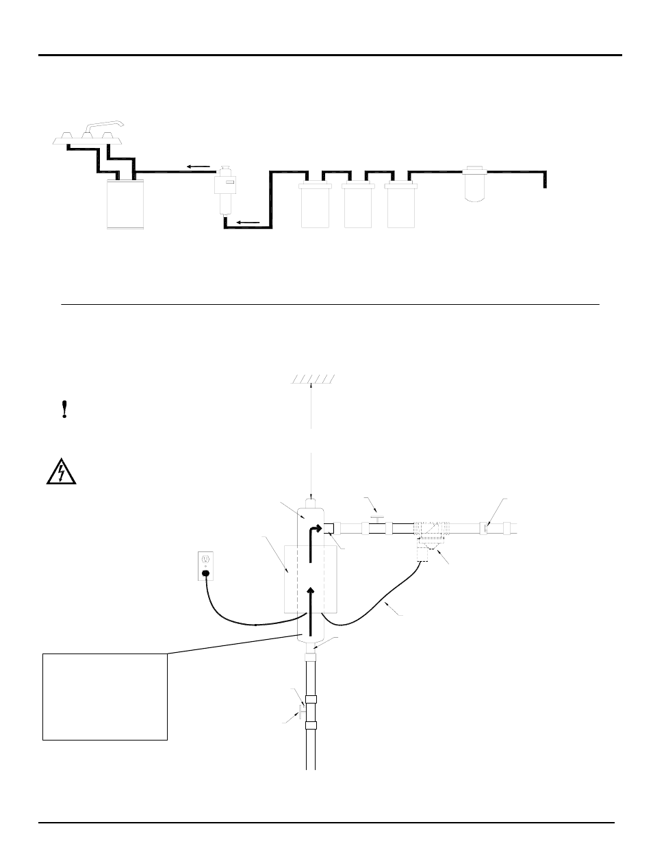
Figure 1 shows a typical installation sequence. Note that all items may not be
necessary for water treatment.
S E D I M E N T
F I L T E R
W A T E R
S O U R C E
S U C H A S S O F T E N E R ,
O P T I O N A L E Q U I P M E N T
O R O D O R F I L T E R
U N I T
U V D I S I N F E C T I O N
H E A T E R
H O T W A T E R
W E D E C O
N O T E : P R E T R E A T M E N T E Q U I P M E N T
M U S T B E I N S T A L L E D P R I O R T O
U V D I S I N F E C T I O N U N I T
Figure 2:
Installation
Planning
You must determine how to run pipes in and out of your disinfection unit.
Figure 2 shows one method of installation (with chamber mounted control
box). Use this diagram to determine the materials needed for your installation.
INLET
OUTLET
FLOW
DIRECTION
SHUTOFF
VALVE
ELECTRICAL
CONTROL BOX
SOLENOID POWER CORD
SHUTOFF
VALVE
*
*
SHUTOFF VALVE MAY BE REQUIRED
TO MEET LOCAL PLUMBING CODES
DRAIN
CAN BE MOUNTED ON THE UNIT OR SEPARATELY
ON THE WALL. CHECK YOUR LOCAL ELECTRICAL
CODES.
**
**
MINIMUM CLEARANCE
IS LENGTH OF UNIT
PLUS 4"
FLOW
RESTRICTOR
SHUTOFF VALVES SHOULD BE
INSTALLED BEFORE AND AFTER
THE DISINFECTION CHAMBER
ELECTRICAL
OUTLET
UV DISINFECTION
CHAMBER
OPTIONAL SOLENOID
VALVE
The disinfection chamber must
be properly grounded to a
suitable electrical ground.
Check local electrical codes for
proper location. Attach ground
wire (not included) to stud and
nut located on lower area of
disinfection chamber.
IMPORTANT!
Check local plumbing
codes for sizes and types of
pipes to be used.
ELECTRIC SHOCK!
Check for hidden electrical
wiring before drilling
holes.
6