Installation instructions, Figure 2, Figure 1 – Hydrotech 6700 Valve Upflow Automatic Water Softeners Operation Manual User Manual
Page 3
2
Installation Instructions
All government codes and regulations governing the installation of these devices must be observed.
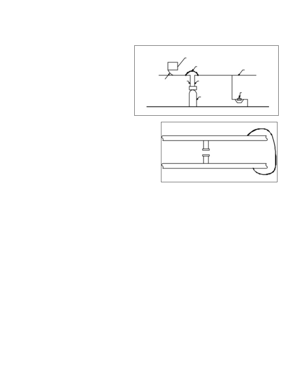
CAUTION: If the ground from the electrical panel or
breaker box to the water meter or underground
copper pipe is tied to the copper water lines and
these lines are cut during installation of the Noryl
bypass valve and/or poly pipe, an approved
grounding strap must be used between the two lines
that have been cut in order to maintain continuity. The
length of the grounding strap will depend upon the
number of units being installed and/or the amount of
copper pipe being replaced with poly. See Figure 1.
In all cases where metal pipe was originally used and
is later interrupted by poly pipe or the Noryl bypass valve as in
Figure 1 or by physical separation as in Figure 2, an approved
ground clamp with no less than #6 copper conductor must be
used for continuity, to maintain proper metallic pipe bonding.
Check your local electrical code for the correct clamp and cable
size.
1. Position the conditioner on a flat surface, near a drain and a
115 volt AC outlet. The unit is provided with a 24V adapter.
2. Study the layout of the present water lines and drains in order that you can determine the best location for your water
conditioner and plan your installation. Your conditioner must not be subjected to freezing or to water temperatures
above 110°F which will void the warranty.
3. All plumbing should be done in accordance with local plumbing codes. The pipe size for the drain line should be a
minimum of 1/2”. However, a 3/4” drain line is required where backwash flow rates are in excess of 7 gpm or the
length of the drain line is greater than 20 feet.
4. Soldering joints near the drain must be done prior to connecting the drain line flow control (DLFC). Leave at least 6”
between the DLFC and the solder joints when soldering pipes that are connected on the DLFC. Failure to do this
could cause interior damage to the DLFC.
5. Teflon tape is the only sealant to be used on the drain fitting.
6. Make sure that the floor is clean and level beneath the salt storage tank.
7. Place approximately 1” of water above the grid plate. If a grid is not utilized, fill to the top of the air check in the salt
tank. Do not add salt to the brine tank at this time.
8. On units with a bypass, place in BYPASS position. Turn on the main water supply. Open a cold soft water tap nearby
and let run a few minutes or until the system is free from foreign material (usually solder) that may have resulted from
the installation. Once clean, close the water tap.
9. Place the bypass in the SERVICE position and let water flow into the mineral tank. When water flow stops, slowly
open a cold water tap nearby and let run until the air the air is purged from the unit.
10. Plug unit into an electrical outlet. NOTE: all electrical connections must be connected according to local codes.
Figure 2
Outside Water Line For Outside
& 3rd Tap Comes From Meter
Filtered Water Line in Home
Unfiltered Water Bypass
Loop Cut & Capped
Ground Strap Required
Because of Break in Continuity
Figure 1
Electrical Panel
Ground Strap
Poly Pipe
Ground
From
Panel
Poly Pipe
Softener
c/w Plastic Bypass
Copper Pipe
Water Meter