Hydrotech C, C PLUS, A PLUS, E, E-DC and E PLUS Series PULSAtron User Manual
Page 16
16
•
When the “ON” signal pulse is input, the pump operates one stroke
and the fluid is discharged. In addition, the pump can be operated
continuously at a rate of up to 125 strokes/min. by repeated input of
“ON” and “OFF” signals.
•
After receiving an input signal, the pump generates the necessary
power pulse to actuate the solenoid. The external signal input is
debounced by the pump circuit. The pump will not stroke in response
to a spurious or erratic input signal that follows at a rate greater than
125 spm. If the external signal rate exceeds 125 spm, the pump will
stroke at half the external signal rate to prevent overdosing and to
protect the pump from overheating.
•
The input signal must be in the form of closure of a mechanical relay,
other mechanical switching device, or of a solid-state switching
device. Voltage signals are prohibited. The switching resistance of
either mechanical or solid-state devices must be 100 ohms or below
when ON and 1 megohm or above when OFF. If any type of solid-state
device is employed, it must be installed with proper polarity, if required
for the device; and leakage current must not exceed 200 microamperes
to prevent false triggering in the OFF state.
•
Cycle rate of the input signal should not exceed 125 times per minute.
•
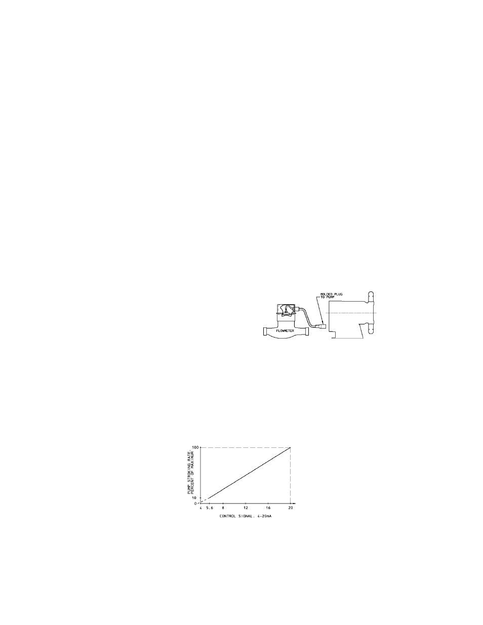
Typical wiring is shown at right
for use with switch closure
flowmeters. (Figure 12)
•
10 millisecond contact time re-
quired for each “ON” input sig-
nal.
5.5.3 4-20mA DC INPUT FUNCTION (E Plus only)
The pump’s stroke rate can also be controlled by a 4-20 mA DC signal to the
terminal marked [4-20 mA].
•
For the 4-20 mA input to have any effect on the pump output rate, the
AUTO/OFF/MANUAL switch must be in the AUTO position.
•
The 4-20 mA input signal affects the pump’s outputs as per the graph
below:
FIGURE 12
FIGURE 13