How your 7000sxt-df water conditioner works, Performance data sheet and specification, Control operation during regeneration – Hydrotech 7000 SXT Valve Water Softener User Manual
Page 2
1
How Your 7000SXT-DF Water Conditioner Works
Hard water enters your home through the main supply line, enters the softener and passes down through a resin mineral
bed which softens the water. An ion exchange process takes place in which the resin beads capture and hold calcium and
magnesium, the hardness minerals, while the water takes on sodium ions. The soft water then flows into your household
water line.
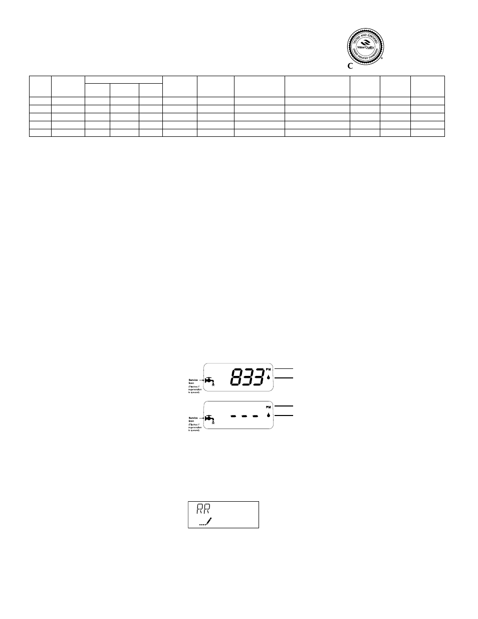
In normal operation, the Time of Day display will alternate being viewed with the Volume Remaining display. This display
will be in gallons, liters or cubic meters. As treated water is used, the Volume Remaining display will count down from a
maximum value to zero or (---). Once this occurs, a regeneration cycle will be initiated at the Set Regeneration Time. Water
flow through the valve is indicated by the Flow Indicator that will flash in direct relationship to flow rate.
Example
833 Gallons of Treated
Water Remaining
0 Gallons of Treated
Water Remaining
Control Operation During Regeneration
In regeneration, the control will display a special regeneration display. In this display, the control will show the current
regeneration step number the valve is advancing to or has reached and the time remaining in that step. The step number
displayed will flash until the valve has completed driving into this regeneration step position. Once all regeneration steps
have been completed, the valve will return to Service and resume normal operation.
Example
Less than 6 minutes
remaining in Regen
Step Rapid Rinse
Pushing the Extra Cycle Button during a regeneration cycle will immediately advance the valve to the next cycle step
position and resume normal step timing.
5
PM Indicator
PM Indicator
Flow Indicator
(Flashing with water flow)
Flow Indicator
(Flashing with water flow)
WQA Tested and
Certified against
CSA B483.1
Performance Data Sheet and Specification
Item No.
Model
Number
Capacity - Grains
Service
Flow Rate
USGPM (LPM)
Maximum
Flow to Drain
USGPM (LPM)
Resin
Tank Size
inches (mm)
Brine
Tank Size
inches (mm)
Resin
Volume
cu. ft (litres)
Salt
Capacity
lbs (kg)
Shipping
Weight
lbs (kg)
@ 15 lbs
/cu.ft
Factory @
10 lbs/cu.ft
@ 6 lbs
/cu.ft
7610
7000MI-30
30
27
20
10.0 (37.9)
2.0 (7.6)
9 x 48 (229 x 1219)
18 x 35 (457 x 889)
1.00 (28.3)
224 (101.6)
85 (38.6)
7611
7000MI-45
45
41
30
12.0 (45.4)
2.4 (9.1)
10 x 54 (254 x 1372)
21 x 36 (533 x 914)
1.50 (42.5)
308 (139.7)
125 (86.7)
7612
7000MI-60
60
55
40
13.0 (49.2)
3.5 (13.2)
12 x 52 (305 x 1321)
21 x 36 (533 x 914)
2.00 (56.6)
308 (139.7)
150 (68)
7613
7000MI-90
90
82
60
15.0 (56.8)
5.0 (18.9)
14 x 65 (356 x 1651)
21 x 36 (533 x 914)
3.0 (84.5)
308 (139.7)
235 (106.6)
7614 †
7000MI-120
120
108
80
20.0 (75.7)
7.0 (26.5)
16 x 65 (406 x 1651)
21 x 36 (533 x 914)
4.0 (113.3)
308 (139.7)
330 (149.7)
† Not certified by WQA
Working Temperature = 34-110°F (1-43°C)
(Do not subject the unit to freezing temperatures)
Working Pressure = 20-125 PSIG (137-861 kPa)
Voltage = 120V / 60 Hz
Pipe Size = 1”
• At the stated service flow rates, the pressure drop through these devices will not exceed 15 psig.
• Capacities of softeners may deviate from the chart above depending on flow rates and raw water conditions.
• The manufacturer reserves the right to make product improvements which may deviate from the
specifications and descriptions stated herein, without obligation to change previously manufactured products
or to note the change.
* Do not use water that is microbiologically unsafe without adequate disinfection before or after the system.