General residential installation check list, Valve installation and start-up procedures – Hydrotech 6700 XTR Valve Downflow Automatic Water Softeners Service Manual User Manual
Page 4
Page
General Residential Installation Check List
Water Pressure
A minimum of 20 psi water pressure is required for regeneration valve to operate effectively.
Electrical Facilities
An uninterrupted alternating current (A/C) supply is required. Please make sure voltage supply is compatible with
unit before installation.
Existing Plumbing
Condition of existing plumbing should be free from lime and iron buildup. Replace piping that has heavy lime and/
or iron build-up. If piping is clogged with iron, install a separate iron filter unit ahead of the water softener.
Location of Softener and Drain
Locate the softener close to a clean working drain and connect according to local plumbing codes.
Valve Installation and Start-Up Procedures
Bypass Valves
Always provide for the installation of a bypass valve if unit is not equipped with one.
Place the softener tank where you want to install the unit.
NOTE: Be sure the tank is level and on a firm
base.
During cold weather it is recommended that the installer warm the valve to room temperature before
operating.
Perform all plumbing according to local plumbing codes..
— Use a 1/2” minimum pipe size for the drain..
— Use a 3/” drain line for backwash flow rates that exceed 7 gpm or length that exceeds 20’ (6 m).
Cut the 1” distributor tube (1.050 O.D.) flush with top of each tank.
Lubricate the distributor o-ring seal and tank o-ring seal. Place the main control valve
on the tank.
NOTE: Use only non-petroleum based silicone lubricant.
Solder joints near the drain must be done before connecting the Drain Line Flow
Control fitting (DLFC).
Leave at least 6” (152 mm) between the DLFC and solder joints when soldering pipes
that are connected on the DLFC. Failure to do this could cause interior damage to
DLFC. Use only Teflon tape on the drain fitting.
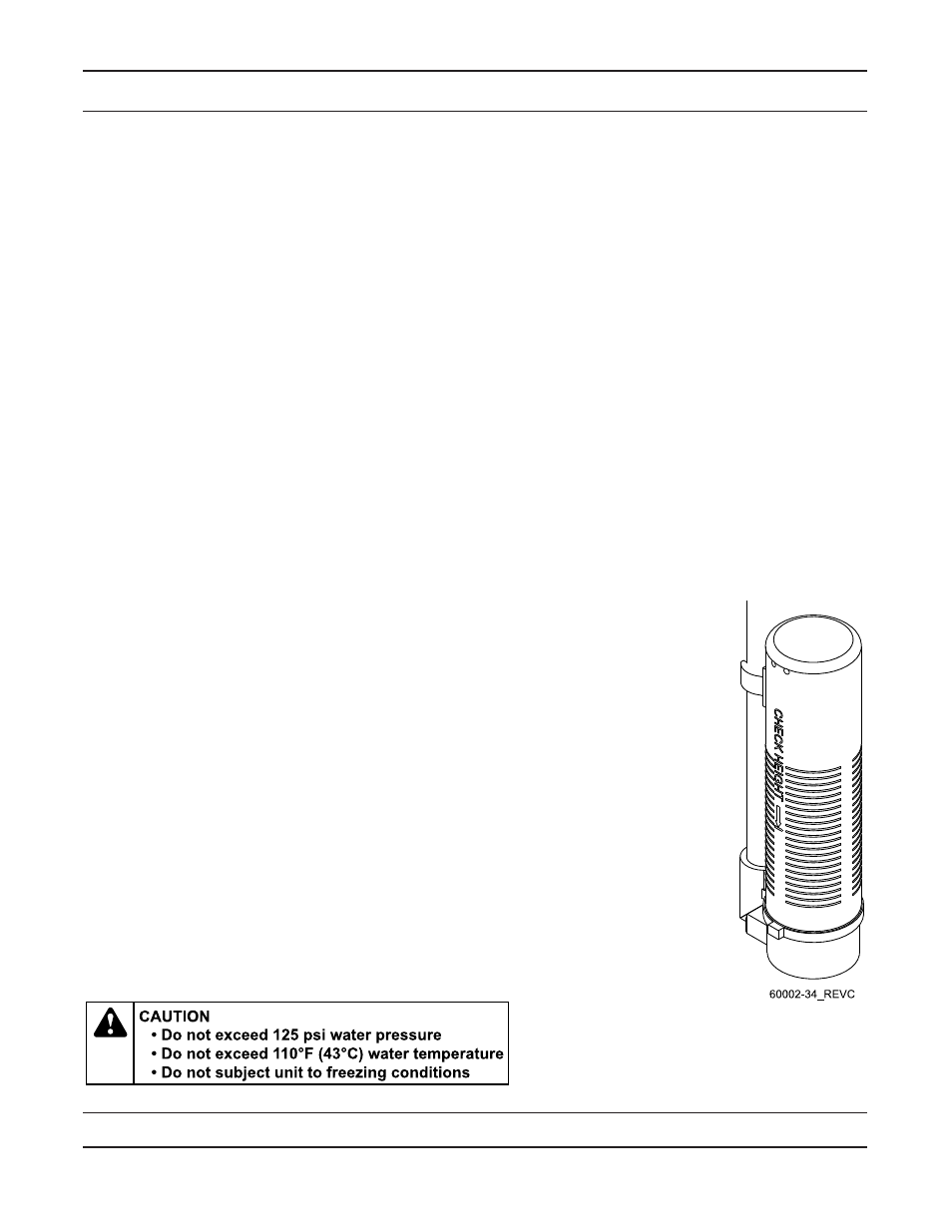
Be sure the floor under the salt storage tank is clean and level.
With a grid plate ensure the air check fill mark is above the grid plate. With or without a
grid plate, fill the brine tank with water to the mark indicated on the air check assembly.
See illustration to the right.
On units with a bypass, place in the bypass position..
— Turn on the main water supply. .
— Open a cold soft water tap nearby and let water run a few minutes or until the
system is free of foreign material (usually solder) resulting from the installation. Close
the water tap when water runs clean.
Place the bypass in the in service position and let water flow into the mineral tank.
When water flow stops, slowly open a cold water tap nearby and let water run until air
is purged from the unit. Then close tap.
Plug the valve into an approved power source. When the valve has power it drives to
the in service position.
1.
2.
3.
4.
5.
6.
7.
8.
9.
10.
11.
12.
13.