Global Specialties PB-502 - Manual User Manual
Page 10
10
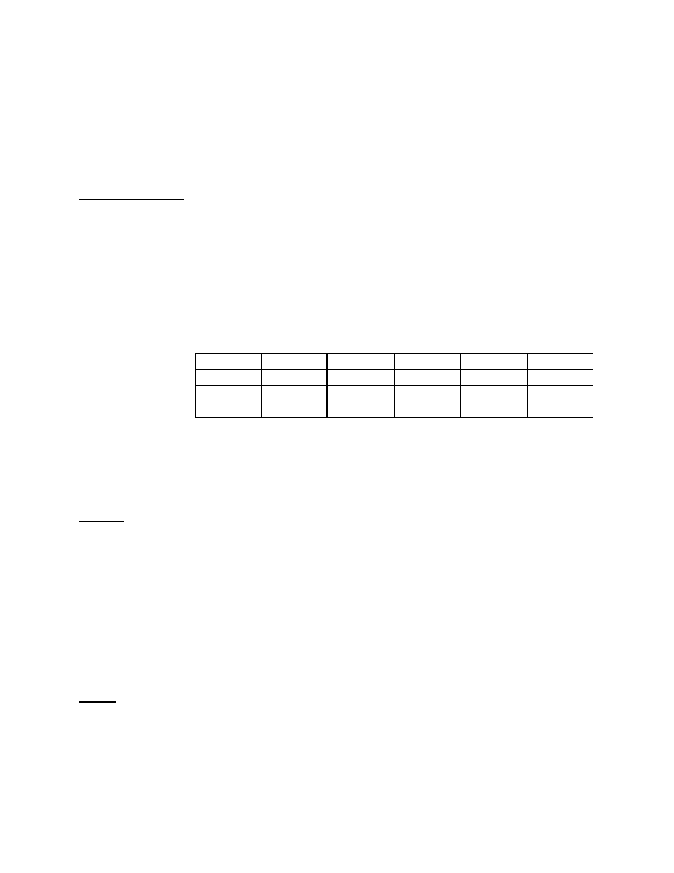
EXTERNAL CAPACITOR
RESULTING OUTPUT FREQUENCY
number displayed can be latched by a low-to-high transition on the LE (Latch Enable)
input. This latched condition will exist as long as a logic 1 is maintained; when LE is
returned to a logic 0, or low, the displays will be restored to their real time status. At any
time the displays are enabled, a Lamp Test can be performed by applying a logic 0 to
the LT tie point associated with the display. This will confirm the proper functioning of
each display by lighting all LED segments.
Frequency Switch
The three position frequency switch, S9, is used to select the output frequency of the
clock. This output is available as either 1Hz, 1kHz, or 100kHz. The Clock Out amplitude
is dependent upon the jumper installed in the CMOS/TTL selector S8, being 12 volts in
the CMOS position and 5 volts in the TTL position. Frequency can also be changed by
inserting a capacitor in the EXT CAP tie points. Some representative capacitors and
their effect on a frequency are shown in Table 1.
0.001MF 0.01
M
F
0.1
M
F
1.0
M F
10 U F
1Hz
1Hz
1Hz
0.91Hz
0.5Hz
0.091Hz
1kHz
500Hz
90.9Hz
9.9HZ
1HZ
0.1Hz
100kHz
50 kHz
9.09kHz
990Hz
100Hz
10Hz
Table 1: Output Frequency vs. External Capacitor Value
Pulsers
Pulsers PBI and PB2 are two fully debounced pushbuttons with true and
complementary outputs. These outputs are made available on the tie-point connector
as PB1 (trigger low), PB1 (trigger high), PB2 (trigger high) and PB2 (trigger low) . The
PB1 output will be at a logic 1 while PB1 is not pressed and will go to a logic 0 when the
switch is pressed, and return to a logic 1 when the switch is released. The PB1 (trigger
high) provides the complement of the above, that is, the point will be at a logic 0 while
the switch is not pressed, will go to a logic 1 while the switch is pressed, and return to a
logic 0 when the switch is released. The operation of PB2 is identical. In all cases, the
logic 1 value is dependent upon the jumper installed in the CMOS/TTL selector, being
12 volts in the CMOS position and 5 volts in the TTL position.
BNCS
Two additional connectors, BNC 1 and BNC 2, are provided to simplify input and output
interfacing to the PB-502. The shells of both BNCs are connected to ground, while the
pins of each individual BNC are connected to adjacent single tie points which can be
wired to the solderless breadboard using jumper wires.
FREQ SW
SETTING