GeneralAire GA50A20 User Manual
Page 5
5
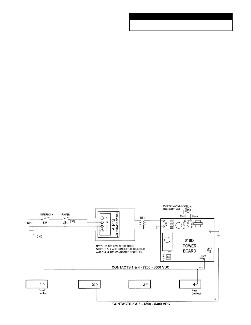
Fig. 5
— Air Cleaner Schematic (with Air Proving Switch)
Electronic Air Cleaner Installation
1. Remove existing equipment filter. Thoroughly clean
fan compartment and ductwork where Air Cleaner is
to be installed.
2. Open access door. Slide filters and collecting cells
out of cabinet.
3. Place cabinet in ductwork. Holes are provided to
attach cabinet to ductwork or equipment. If the
adjoining ductwork is flanged, install the screws so
that the screw heads are inside the cabinet. This will
help prevent damage to prefilter and carbon filters
during removal for cleaning. Never put screws or
rivets
into
the
removable
power
box.
When the air duct does not fit the Air Cleaner
opening, a gradual transition is recommended to
reduce air turbulence though the air Air Cleaner and
to increase its efficiency. There should not be more
than 20º of expansion used on each side of the
transition fitting. Do not reduce ductwork to a smaller
Air Cleaner or it will increase the velocity of airflow.
4. If the Air Cleaner is installed adjacent to an elbow or
angle fitting, turning vanes are recommended to
improve air distribution across the collecting cells.
5. After the Air Cleaner has been installed, seal seams
airtight with duct tape or caulking to prevent dust
from entering the system.
6. Replace the prefilters in the track on the air entering
side. Place the carbon filters evenly spaced in the
track on the air exiting side. The collecting cells are
placed between the tracks, with the arrow on cell
pointing towards the fan. The cell handle may need
to be repositioned if the airflow is in a different
direction than the left to right set up. The handle
should face the door. Close access door.
Wiring
Wiring should only be performed by qualified
personnel only. All wiring must comply with all applicable
codes and standards. The voltage of the power source
must match the voltage indicated on the Air Cleaner. The
Air Cleaner must operate ONLY when the system fan is
running. Make sure the Air Cleaner is properly grounded.
If the air cleaner is equipped with a cord and plug the
air cleaner can be plugged into an outlet within 6 feet of
the unit. Do not use an extension cord if the outlet is too
far away. Have an electrician wire in a new outlet closer
to the air cleaner.
If the air cleaner is not equipped with a cord then wire
the Air Cleaner directly to a 120 V power source
preferably to the same source that is supplying power to
the furnace or air handler. The APS will power the Air
Cleaner when there is sufficient airflow to activate the
sensor. See Fig 5.
Note: The power switch will be lit even if there is no
airflow.
If the unit is to be wired to the EAC contacts on the
system module check that there is sufficient voltage to
the EAC contacts with the fan operating in all conditions.
Some systems do not power the contacts on low speed.
SYSTEM CHECK
Perform the following system check before operation.
1. Replace prefilters, collecting cells and carbon filters.
Close access door.
2. Turn Air Cleaner power switch ON. Ensure system
fan is operating. Both the power switch light and
performance indicator light should be lit. The power
switch light indicates the Air Cleaner has unit voltage.
The performance indicator light shows that the Air
Cleaner is operating.
WARNING
Electrical shock can cause injury or death. Be certain
main line disconnect switch is off before wiring.