GeneralAire GA50A20 User Manual
Page 3
where they are attracted to a series of grounded plates.
Pollutants are held in this section like a magnet until
washed away during cleaning. Lastly, clean air passes
over activated carbon filters (3) for odor removal .
The Electronic Air Cleaner, available in three models
with air flow capacities of up to 1400 and 2000 CFM
(2380 and 3400 m³/hr), is adaptable to all residential
forced air heating or cooling systems.
COMPONENTS
Cabinet: Constructed of heavy gauge galvanized steel
to resist corrosion and provide trouble-free installation.
Holes are provided to facilitate mounting to the ductwork
or air handling equipment.
Power Box: Removable. Contains the power switch,
performance indicator light, safety interlock switch, high
voltage power board, air proving switch and high voltage
contacts.
The power board is uniquely equipped with a variable
resistor (potentiometer) to adjust high voltage output.
Output has been pre-set for optimum efficiency. As
voltage varies in extreme conditions of dryness, humidity
or proximity to hydro towers, raising or lowering
potentiometer allows for proper voltage output.
Air Proving Switch (APS): Integrated. Automatically
cycles Air Cleaner on and off with the system fan. The
APS will detect airflow (fan on) and energize the Air
Cleaner.
Collecting Cells: Consist of an ionizing section and a
plate section. The arrow on the cell must point toward the
system fan.
Prefilters: Constructed of aluminum mesh, to prevent
lint and large particles from entering the collecting cells.
Carbon Filters: Remove odors. Must be replaced every
six months - not washable. Maximum of (3) carbon filters
can be used at same time.
INSTALLATION
Static Pressure
The static pressure drop across the Air Cleaner will
vary with CFM and whether the optional carbon filters
have been installed in the unit.
Location
The Air Cleaner must only be installed in the return
air duct, as close to the fan compartment as possible.
This location provides the most even airflow across the
collecting cells and allows the Air Cleaner to keep the
system motor and blower clean. The installation can be
vertical or horizontal. When choosing a location, there
must be adequate room to wire the Air Cleaner and
remove prefilters, collecting cells and power box for
maintenance.
Note: Once Air Cleaner has been installed, do not allow
the placement of any device such as a new hot water
heater, water softener, gas pipe, or electrical cable to be
put 2 ft. in front of or within 6 in. (15 cm) from top of Air
Cleaner, in order to allow removal of filters and Air
Cleaner parts, which are necessary for maintenance or
servicing.
Table 1
— SPECIFICATIONS
MODEL
GA50A14
GA50A20
GA50A22
House Size Area
<3000 ft²
<278.70 m²
>3000 ft²
>278.70 m²
<3000 ft²
<278.70 m²
Airflow
up to 1400 CFM
up to 2380 m³/hr
up to 2000 CFM
up to 3400 m³/hr
up to 1400 CFM
up to 2380 m³/hr
Duct Size
16 x 25 in
40.5 x 63.5 cm
20 x 25 in
51.0 x 63.5 cm
20 x 20 in
51.0 x 51.0 cm
Unit Weight
37 lbs
16.8 kg
41 lbs
18.6 kg
37 lbs
16.8 kg
Input Voltage
120 V 60 Hz
120 V 60 Hz
120 V 60 Hz
Power Consumption
30 Watts
30 Watts
30 Watts
Options Included
Carbon Filters
Air Switch
Carbon Filters
Air Switch
Carbon Filters
Air Switch
100% Air Flow
No Carbon
100% Air Flow
With Carbon
40% Air Flow
No Carbon
40% Air Flow
With Carbon
0.158
0.250
0.030
0.060
Table 2
— Pressure Drop (Inches WC)
3
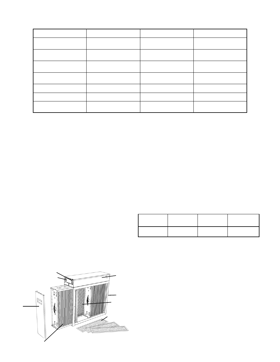
Power Box
Cabinet
Door
Performance Indicator Light
ON/OFF Switch
Collecting Cells (2)
Activated Carbon
Filters (3)
Prefilters (2)
Fig. 2