Biamp TDT300 User Manual
Page 2
FIGURE
5
1. Disconnect AC power from the amplifier.
2. Remove the amplifier top panel by removing 17 screws
(6 on each side, 3 on back and 2 on front).
Please note that front screws are longer.
3. If the mounting bolts have two nuts, remove one and
save. These nuts will be used to hold the transformers
in place. If the mounting bolts have only one nut, do
not remove. Transformer will be held in place with
supplied nut.
4. Install transformers as shown in figure 1.
5. Locate the amplifier circuit boards and jumpers.
Each amplifier card represents two individual output
channels; one odd and one even (refer to figure 2 for
reference).
6. Using a pair of pliers, remove the black and red jumper
from the associated amplifier channel.
7. Following the diagram below (figure 3), connect the
wires as indicated.
Please note that wires on odd channel are
mirrored from wires on even channel.
TDT50 & TDT150 INSTALLATION INSTRUCTIONS
8. Replace amplifier top panel (longer screws go on the
front).
9. Assign channel HPF (High Pass Filter) by flipping the
appropriate channel rear panel dip switch. (figure 4)
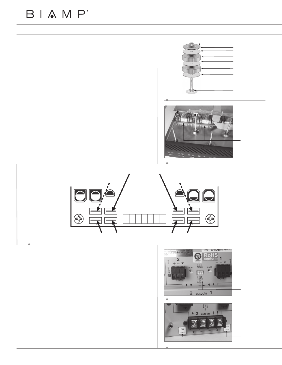
10. Apply appropriate rear panel “xfmr” voltage sticker.
(figure 5)
Odd channel
jumpers (Ch 1)
Even channel
jumpers (Ch2)
Amplifier
Cards
Nut
Metal Dome Washer
Rubber Washer
Transformer
Rubber Washer
Transformer
Rubber Washer
Bolt
Even
Channels
(2, 4, 6, & 8)
Odd
Channels
(1, 3, 5, & 7)
Brown wire = 25V
Orange wire = 70V
Yellow wire = 100V
Brown wire = 25V
Orange wire = 70V
Yellow wire = 100V
Blue wire
Blue wire
Green wire
Green wire
Black wire
Black wire
Affix transformer
stickers
High Pass Filter
(HPF)
dip switches
FIGURE
1
FIGURE
2
FIGURE
4
FIGURE
3