Flowline LV42 Switch-Tek User Manual
Page 7
Rev A
MN301200
7 of 10
INSTALLATION
Step Five
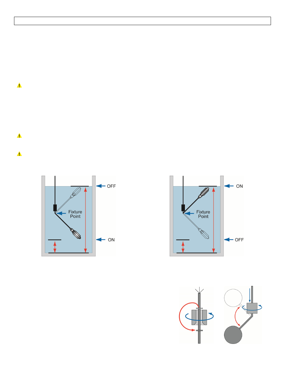
The basic operating principle of the sump float is very simple. As fluid level rises the float will also rise,
resulting in a tilt of the micro‐switch located inside the housing. This tilt will generate a signal that can be
used to actuate a motor or signal an indicator alarm. To ensure the proper function of the sump float, it is
necessary to secure the electric cable inside the tank or well. The length of the cable measured between the
fixture point (see below) and the body of the float determines the total extension of the float. This results in
the distance between the pump stopping and starting level. This distance should be no less than 6 in (15 cm).
It is essential to ensure that there are no obstructions in the sump floats operational area before operation.
Warning: During operation, adjustments to the sump float cable must not be made under any
circumstances due to the fact that any unwanted cable connections made while the sump float is
immersed in water can lead to electric shock.
There are two installation options for this sump float. One method is to fix the cable of the float to the
reservoir or container with the use of a small clamp. Another technique would be to attach the LV49‐7000
counter weight to the float’s cable a desired distance between the highest and lowest level desired.
Note: With the use of the counterweight, the length of cable between the float and fixed point (starting
and stopping indication) can be freely adjusted.
Note: The LV42 series is self counterweighted and can be used without the need of additional
counterweight, clamp, or bracket. The previous are means to simplify installation and aid in organizing the
use of multiple float switches.
Fill Operation ‐ Shown with Counter Weight
Empty Operation ‐ Shown with Counter Weight
INSTALLATION OF COUNTERWEIGHT
For correct counterweight installation, refer to the following procedure as well as the illustration.
1. Insert the cable into the counterweight, turning it. This will
result in the detachment of the plastic ring inserted in the
mouth (if necessary use a screwdriver to aid in the
detachment of the ring). Place the ring at the point on the
cable where the counterweight is to be attached.
2. Attach the counterweight on the ring by turning it and using
moderate pressure. (Counterweight sold separately).