Wiring, Maintenance – Flowline AX13 Switch-Pak User Manual
Page 6
Step Seven
VAC Power Input Wiring:
Observe the labeling on the con-
troller. Note: Polarity does not matter with the AC input terminal.
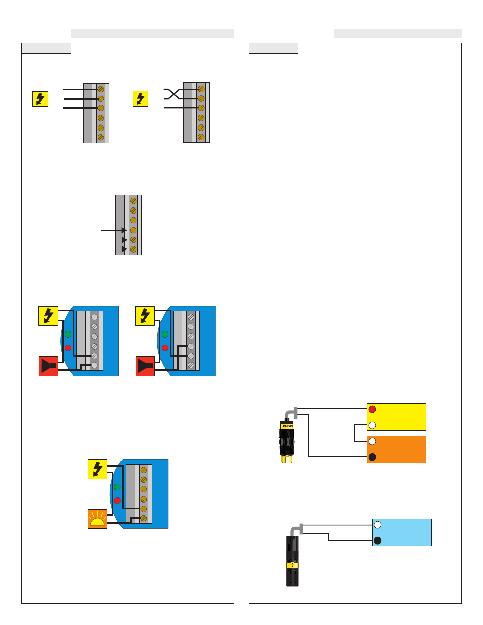
Relay Input Wiring:
The relay is a single pole, double throw
type rated at 250 Volts AC, 10 Amps. The terminals Normally Open
(NO) and Normally Closed (NC) will be used in different applica-
tions. Remember that the "normal" state is when the relay coil is de-
energized and the Red relay LED is OFF (de-energized).
A typical application for the Switch Pak™ with Compact Relay
Controller is to operate a pump or valve between the two set points
(automatic fill or empty). In this application, a pump or valve can be
wired to either the Normally Open (NO) or Normally Closed (NC)
side of the relay.
AC
AC
GND
NC
C
NO
R
P
Strobe
HOT
NRTL
GND
AC
AC
GND
NC
C
NO
AC
AC
GND
NC
C
NO
HOT
NRTL
GND
AC
AC
GND
NC
C
NO
Relay
Terminals
Strobe Alert Output
With the Strobe Alert wired NO, the strobe will flash when the Red
LED is ON (Invert OFF). The strobe will flash when the Red LED is
OFF when wired NC or by turning the Invert ON. If the strobe is
wired NC and the Invert is ON, the strobe will flash when the Red
LED is ON (same as NO wiring and Invert OFF).
AC
AC
GND
GND
NC
NC
C
NO
NO
R
R
P
Alarm
AC
AC
GND
GND
NC
NC
C
NO
NO
R
R
P
Alarm
NO Wiring
NC Wiring
Power to
Switch Pak
not shown.
Power to
Switch Pak
not shown.
Power to
Switch Pak
not shown.
WIRING
Step Eight
MAINTENANCE
General:
The Switch Pak™ with Compact Relay Controller
requires no periodic maintenance except cleaning as required. It is the
responsibility of the user to determine the appropriate maintenance
schedule, based on the specific characteristics of the application liquids.
Cleaning Procedure:
1. Power:
Make Sure that all power to the sensor, controller and/or
power supply is completely disconnected.
2. Sensor Removal:
Make sure that the tank is in a state where it
is safe to remove the sensors. Carefully, remove the Switch Pak™
from the installation.
3. Cleaning the Sensor:
Use a soft bristle brush and mild deter-
gent, carefully wash the Switch Pak™. Do not use harsh abra-
sives such as steel wool or sandpaper, which might damage the
surface sensor. Do not use incompatible solvents which may
damage the sensor's PP or Ryton plastic body.
4. Sensor Installation:
Follow the appropriate steps of installa-
tion as outlined in the installation section of this manual.
Controller Logic:
1. Power LED:
Make sure the Green power LED is On when
power is supplied to the controller.
2. Input LED(s):
The input LED on the controller will be Amber
when the switch is wet and Off when the switch is dry. Note: see
Step 5 regarding reed switches. If the LED's are not switching the
input LED, test the level switch.
3. Relays:
When both inputs are wet (Amber LED's On), the relay
will be energized (Red LED On). After that, if one switch
becomes dry, the relay will remain energized. Only when both
switches are dry (both amber LED's Off) will the controller de-
energize the relay. The relay will not energize again until both
switches are wet. See the Relay Latch Logic Chart below for fur-
ther explanation.
Current Test (Ultrasonic and Vibration only):
Used to verify if the sensor is indicating a wet or dry condition. This
test uses only two wires (Red and Black). The sensor draws 5 mA
(ultrasonic) or 8 mA (vibration) when it is dry, and 19 mA when wet.
The White and Green wires are not used.
Contact Test (Buoyancy only):
Used to verify if the reed switch is switching between dry (open) and
wet (closed). Check for continuity across Black and White (open for
dry and closed for wet). Checking across Black and Red will result
in a closed when dry and open when wet condition.
Red
24 VDC
Power Supply
+
-
Multimeter
(mA)
-
+
Black
White
Black
Multimeter
(Continuity)
-
+
Normally Open
(Dry)