Assembly of switch pak, Safety precautions – Flowline AX13 Switch-Pak User Manual
Page 4
Step Four
ASSEMBLY OF SWITCH PAK™
Step Three
SAFETY PRECAUTIONS
About this Manual:
PLEASE READ THE ENTIRE MANU-
AL PRIOR TO INSTALLING OR USING THIS PRODUCT. This
manual includes information on the Switch Pak™ with Compact
Relay Controller: AU13-_2__, AZ13-_2__ and AV13-_2__. The
units are identical except for the material of construction, choice of
Strobe Alert and the sensors technology.
User's Responsibility for Safety:
Flowline manufactures
a wide range of liquid level sensors, controllers, and mounting sys-
tems. It is the user's responsibility to select components that are
appropriate for the application, install them properly, perform tests
of the installed system, and maintain all components. The failure to
do so could result in property damage or serious injury.
Proper Installation and Handling:
Use a proper sealant
with all installations. Never overtighten the components. Always
check for leaks prior to system start-up.
Material Compatibility:
Polypropylene (PP, a polyolefin): Sensor, Switch Pak™ fitting,
Controller Housing.
Polyvinylidene Fluoride (PVDF): Sensor and SWitch Pak™ fitting.
Viton (a fluorocarbon): O-ring.
Make sure that the application liquids are compatible with the
materials that will be wetted. To determine the chemical compati-
bility between the components and its application liquids, refer to
the Compass Corrosion Guide, available from Compass
Publications (phone 858-589-9636).
Temperature and Pressure:
Switch Pak™ is designed for
use in application temperatures up to 90° C (194° F). The Vibration
and Ultrasonic packages are designed for pressurized applications
up to 150 psi (10 bar) and the Buoyancy package is designed for
use up to 25 psi (1.7 bar).
Wiring and Electrical:
Electrical wiring of any liquid level
control system should be performed in accordance with all applic-
able national, state, and local codes. Take care not to cut or break
the outer insulation jacket of wiring that may be immersed while
routing cables in the Switch Pak™ system. Such breaks of the liq-
uid seal of the sensor system may lead to component failure.
Flammable, Explosive and Hazardous Applications:
The AU13-_2__, AV13-_2__ and AZ13-_2__ Switch Pak™
should not be used within classified hazardous environments.
Make a Fail-Safe System:
Design a fail-safe system that
accommodates the possibility of system or power failure. In criti-
cal applications, Flowline recommends the use of redundant back-
up systems and alarms in addition to the primary system.
About Switch Pak™:
Flowline’s Switch Pak™ with Compact
Relay Controller Assembly is an single-point mounting system for
installing one level sensor vertically within a tank. The compact relay
controller features a 120/240 VAC controller with a 250 VAC, 10A
SPDT relay contract. Switch Pak™ mounts vertically through a stan-
dard 2" NPT (1 1/2” G) tank adapter, or on a side mount bracket (such
as the LM50-1001).
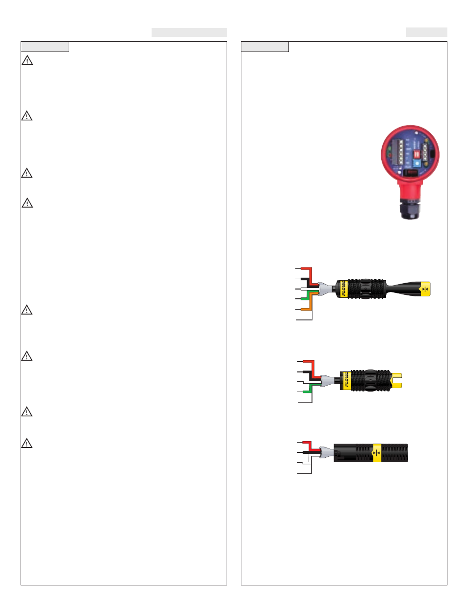
Relay Controller:
The level switch is
pre-wired before shipment to the 2-pole ter-
minal strip [Input 1 (+) & (-)]. The switch
technologies used to indicate level are either
Ultrasonic, Buoyancy or Vibration. The
Compact Relay Controller provides a 1/2”
Conduit connection and 6 poles for wire ter-
mination of power and relay contact. Use the
AC, AC and GND terminals for providing
power. Use the NC, NC and COM terminals
for interfacing to the relay contact.
Vibration (LZ12-1405)
Wire Configuration:
RELAY
Red
Black
White
Green
Orange
(+)
(-)
N/A
N/A
N/A
Shld
RELAY
(+)
(-)
N/A
N/A
Shld
Red
Black
White
Green
REED
N/A
(-)
(+)
Shld
Red
Black
White
Ultrasonic (LU10-_305 or LU10-_325) Wire
Configuration:
Buoyancy (LV10-_301 or LV10-_351) Wire
Configuration:
Compact
Relay Controller
(inside shown)