Wiring, Maintenance – Flowline AX1X Switch-Pak User Manual
Page 6
Step Seven
WIRING
Step Eight
MAINTENANCE
General:
The Switch Pak™ with Compact Junction Box requires
no periodic maintenance except cleaning as required. It is the respon-
sibility of the user to determine the appropriate maintenance schedule,
based on the specific characteristics of the application liquids.
Cleaning Procedure:
1. Power:
Make Sure that all power to the sensor, controller and/or
power supply is completely disconnected.
2. Sensor Removal:
Make sure that the tank is in a state where it
is safe to remove the sensors. Carefully, remove the Switch Pak™
from the installation.
3. Cleaning the Sensor:
Use a soft bristle brush and mild deter-
gent, carefully wash the Switch Pak™. Do not use harsh abra-
sives such as steel wool or sandpaper, which might damage the
surface sensor. Do not use incompatible solvents which may
damage the sensor's PP or Ryton plastic body.
4. Sensor Installation:
Follow the appropriate steps of installa-
tion as outlined in the installation section of this manual.
Testing the installation:
1. Power:
Turn on power to the switches and/or power supply.
2. Immersing the switch:
Immerse the sensing tip of each switch
in its application liquid, by filling the tank up to the switches point
of actuation. An alternate method of immersing the switch during
preliminary testing is to hold a cup filled with application liquid
up to the switch's tip.
3. Test:
With the switch being fluctuated between wet and dry
states, the switch will open or close depending on wiring status.
If the system doesn't have an input indicator, use a multimeter to
ensure that the switch produces the correct signal.
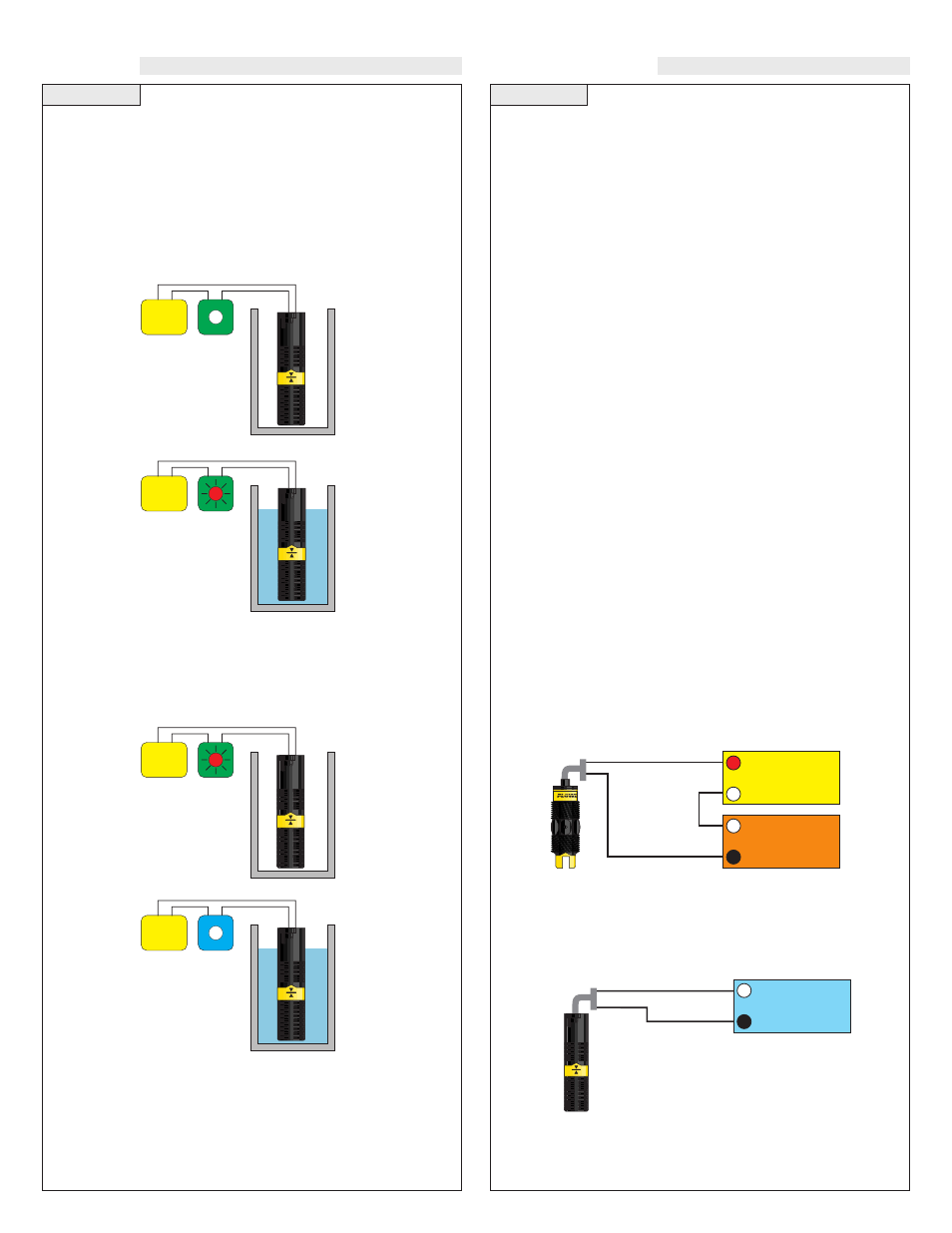
Current Test (Ultrasonic and Vibration only):
Used to verify if the sensor is indicating a wet or dry condition. This
test uses only two wires (Red and Black). The sensor draws 5 mA
(ultrasonic) or 8 mA (vibration) when it is dry, and 19 mA when wet.
The White and Green wires are not used.
Contact Test (Buoyancy only):
Used to verify if the reed switch is switching between dry (open) and
wet (closed). Check for continuity across Black and White (open for
dry and closed for wet). Checking across Black and Red will result
in a closed when dry and open when wet condition.
Red
24 VDC
Power Supply
+
-
Multimeter
(mA)
-
+
Black
White
Black
Multimeter
(Continuity)
-
+
Normally Open
(Dry)
Buoyancy Level Switch (LV10-1301 & LV10-1351):
The LV10-13_1 switch can be wired normally open or normally
closed for your application requirement.
Normally Open:
Use the Black and White wires for operating the LV10-_3_1 in a nor-
mally open state. Normally open is defined as the switch being open
when the float is dry and closed when the float becomes submersed.
This operation is typical for indicating a high level.
Normally Closed:
Use the Black and Red wires for operating the LV10-_3_1 in a nor-
mally closed state. Normally closed is defined as the switch being
closed when the float is dry and open when the float becomes sub-
mersed. This operation is typical for indicating a low level.
White
Power
Supply
Black
White
Power
Supply
Black
Red
Power
Supply
Black
Red
Power
Supply
Black