Mounting the echopod – Flowline DL10 EchoPod User Manual
Page 5
We do Your Level Best
We do Your Level Best
Configuration Settings
Mounting the EchoPod
®
The EchoPod
®
should always be mounted perpendicular to the liquid surface and
installed using the provided Viton
®
mounting gasket. Always use fittings, with thin wall
mounting structures that isolate the transducer. This will provide the best performance
over the lifetime of the product.
The preferred mounting fitting for the EchoPod
®
DL10 is the reducer bushing LM52-
1400 (2” thread x 1” thread). Further mounting products and solutions can be found
on the Flowline website a
An instructional video on mounting
ultrasonic level measurement technology is also available on the website.
For installations in existing 2” fittings:
1) Use LM52-
1400 2” thread x 1” thread adapter (An
adapter with an air gap around the 1 inch threads as
shown is recommended).
For installations in plastic tanks:
1) Use a Bulkhead fitting LM52-1890
1” inch Bulkhead
fitting,
2) Use a Bulkhead fitting LM52-2890 in combination with
LM52-1400 or,
3) Weld a plast
ic 1” half coupler to tank top.
For installations in metal tanks:
1) Use the recommended bulkhead fittings as shown
above or a LM52-
1850 1” Flange. The flange fitting
must have a riser for the threaded section. Drilling and
tapping a blind flange is not recommended.
2)
While installations directly into a 1”metal fitting are not
recommended, acceptable results may be obtained if
the 1” fitting is a half coupling in form and the outer
diameter of the coupler is tightly wrapped in vinyl tape
to dampen vibrations.
For installations in open tanks and sumps:
1) Use Flowline's LM50-1001-1 side mount bracket,
which includes a 2" x 1" thread reducer bushing.
Using the drop-down menus on the left of the WebCal screen, set the configuration
for your application requirements. When a selection does not apply to your
application
, “Not Applicable” will appear in the drop-down. Make sure all drop-downs
are set appropriately for your application before moving to the Tank Level section.
NOTE: If you would like to start over, click the
Clear Screen button on the right.
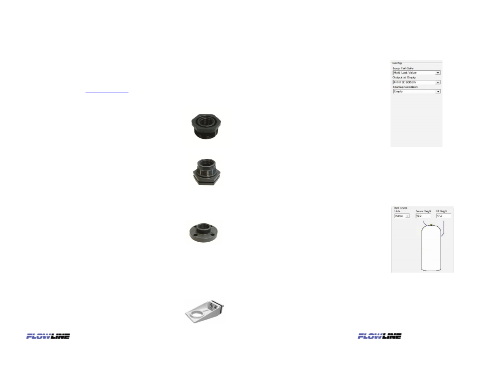
Enter the appropriate tank level set points for your application.
Tank Level Settings
Units. Display measurements in inches
or centimeters.
Sensor Height. Distance measured from
the bottom of the empty tank to the
bottom of the transducer. Under factory
configuration, this becomes the 4 mA set
point.
Fill Height. Distance measured from the
bottom of the empty tank to the maximum
fill height within the tank. Under factory
configuration, this becomes the 20 mA
set point.