Out 1 and 2 – non-isolated, Out 3 and 4 – opto-isolated – ALLIED Vision Technologies Prosilica GT6600 User Manual
Page 63
Camera interfaces
AVT Prosilica GT Technical Manual V2.1.0
63
Out 1 and 2 – non-isolated
Out 1 and Out 2 signals are not electrically isolated and can be used when envi-
ronmental electrical noise is inconsequential and faster trigger response is
required. Tie signal ground to Camera GND to complete the external circuit. The
output signal is a low voltage TTL, maximum 3.3 V. Not suitable for driving
loads in excess of 50 μA.
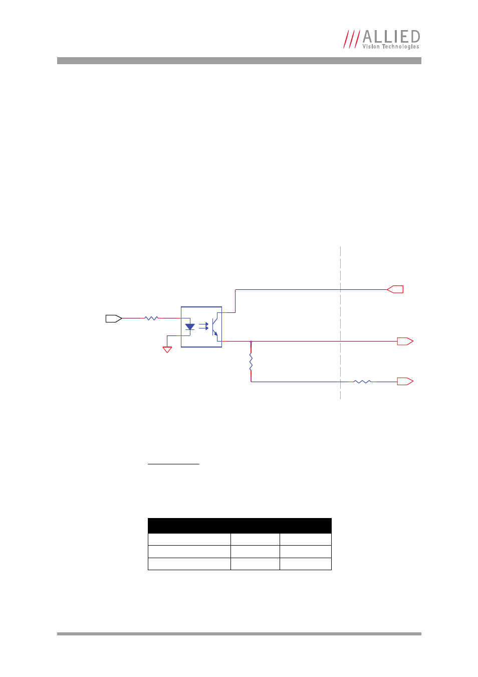
Out 3 and 4 – opto-isolated
Out 3 and Out 4 signals are optically isolated and require the user to provide a
voltage level, Isolated Out Power. Tie signal ground to Isolated IO GND to
complete the external circuit. Isolated Out Power can be configured between
5–24 V. An example of the functional circuit is indicated in the following dia-
gram.
Trigger current, and OUT ICC are a function of Isolated Out Power voltage.
Figure 45: Prosilica GT Out 3 / Out 4 trigger circuit
Note
If Isolated Out Power = 24 V, an additional load resistance, R
is required to limit OUT ICC.
Isolated Out Power
OUT ICC
R LOAD
5 V
1.0 mA
0 Ω
12 V
2.5 mA
0 Ω
24 V
1.2 mA
15 KΩ
Table 24: Prosilica GT trigger circuit values
OUT 3 / OUT 4
422R
ISOLATED OUT POWER
4.75 K
ISOLATED IO GND
EXTERNAL
CAMERA INTERNAL
TCMT1107
1
2
4
3
3.3 V CAMERA
LOGIC SIGNAL
R
- Prosilica GT4907 Prosilica GT4905 Prosilica GT3400 Prosilica GT3300 Prosilica GT2750 Prosilica GT2450 Prosilica GT2300 Prosilica GT2050 NIR Prosilica GT2050 Prosilica GT2047 Prosilica GT2000 NIR Prosilica GT2000 Prosilica GT1920 Prosilica GT1910 Prosilica GT1660 Prosilica GT1600 Prosilica GT1380 Prosilica GT1290