Flo-trex combination valve – AAON LN-140 User Manual
Page 49
49
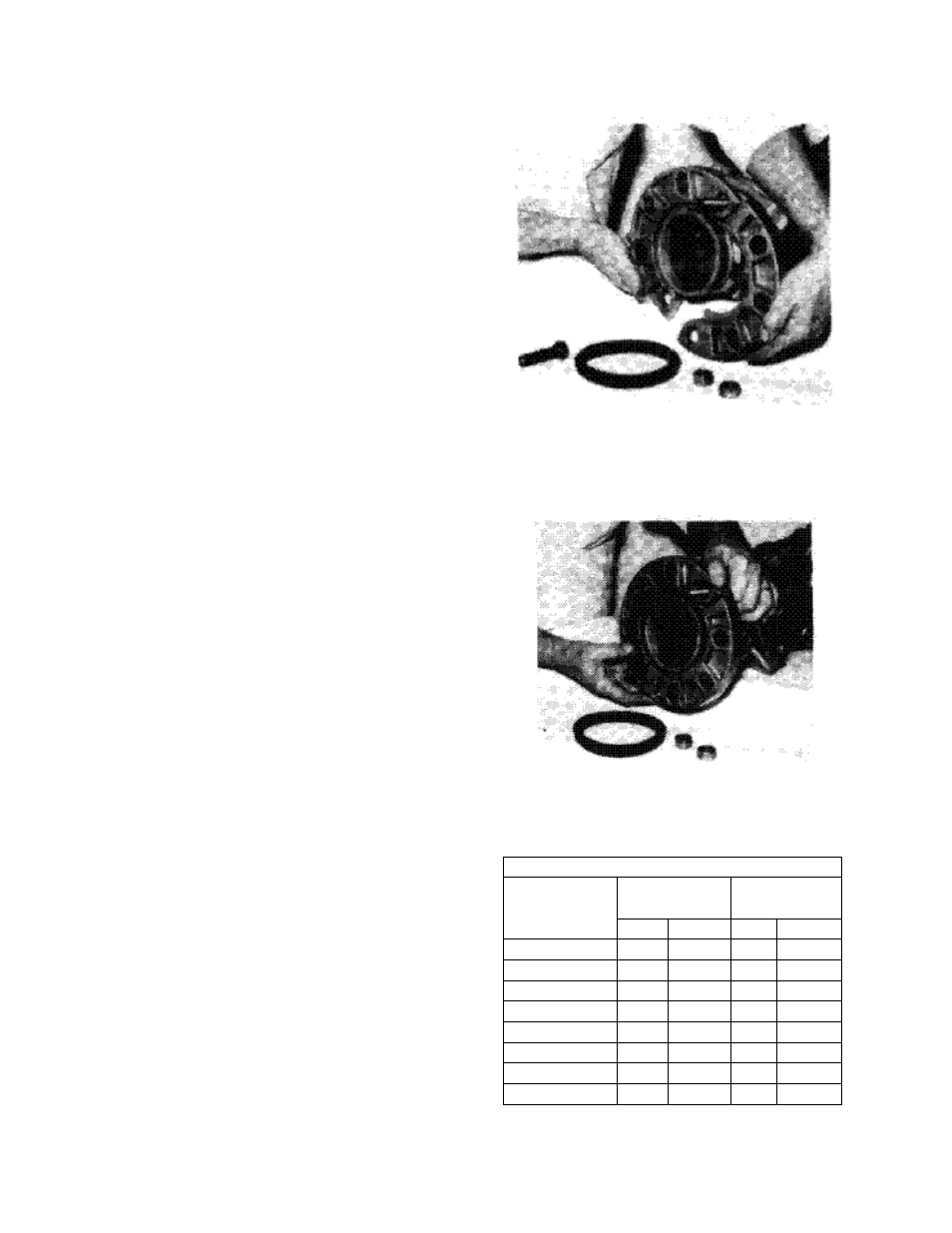
systems and could easily clog with debris if
left in place. This will be detrimental to the
operation of the pump.
Inspect the cover O-ring and replace if
necessary.
Replace the permanent strainer into the
fitting body, once the temporary strainer is
removed.
Replace the cover into the body. Ensuring
that the strainer is properly seated, tighten
the cover bolts diagonally, evenly and
firmly.
Flo-Trex Combination Valve
Introduction
The Flo-Trex combination valves are
designed for installation on the discharge
side of centrifugal pumps, and incorporate
three functions in one valve:
1. Drip-tight shut-off valve
2. Spring closure design, Non-slam check
valve
3. Flow throttling valve
Armgrip Flange Adapter Installation
1. Position the two halves of the Armgrip
flange adapter on the valve body
ensuring that the lugs on each half of the
flange adapters are located between the
anti-rotation lugs on the valve body (as
shown).
Insert two bolts of specified size (Table A1)
to secure the halves of the flange adapter to
the valve body (as shown).
Table A1. Armgrip Flange Adapter Details
Valve Size
125 psi/150 psi 250 psi/300 psi
Ductile Iron Bolt Ductile Iron Bolt
No.
Size
No.
Size
2-1/2
4
5/8
8
3/4
3
4
5/8
8
3/4
4
8
5/8
8
3/4
5
8
3/4
8
3/4
6
8
3/4
12
3/4
8
8
3/4
12
7/8
10
12
7/8
16
1
12
12
7/8
16
1-1/8