AAON CN-140 User Manual
Page 28
28
6. Determine the current blade pitch and the pin location for the new blades
Table 3 - Condenser Fan Pin Location
Type
Bushing
Mount
Blade Pitch Angle
20°
25°
28°
30°
33°
35°
38°
40°
45°
50°
5Z
A
-
RET
-
RET
RET
RET
HUB
HUB
HUB
HUB
B
-
HUB
-
HUB
HUB
HUB
RET
RET
RET
RET
Table 4 - Condenser Fan Pin Location
Type
Rot.
Blade Pitch Angle
20°
25°
28°
30°
33°
35°
38°
40°
45°
50°
5Z
R
-
4
-
3
2
1
4
3
2
1
L
-
1
-
2
3
4
1
2
3
4
7. Replace fan blades in the new pin
location and reassemble the fan
Replace the blades with the pin in the 1, 2,
3, or 4 groove position of either the HUB or
RET. Assemble the fan making sure to place
the blades in their previous blade sockets, to
match up the previous orientation of HUB
and RET and to replace any balancing
weights in their previous locations. Tighten
bolts in a cross pattern to 5-6 ft-lbs. of
torque.
Multi-Wing W Series Black Glass
Reinforced Polypropylene Fan Blade Pitch
Angle Setting Instructions
Contact the AAON parts department to
acquire the new pitch pins for the fan blades.
Note original position of retaining plates,
center boss and all hardware including
additional hardware used for balancing.
1. Remove all the bolts and nuts.
2. Determine blade rotation – on the
concave side of the blade is a blade marking
showing 6WR, 6WL, 7WL, 7WR, or 9WR.
The “L” and “R” denote the rotation of the
blade.
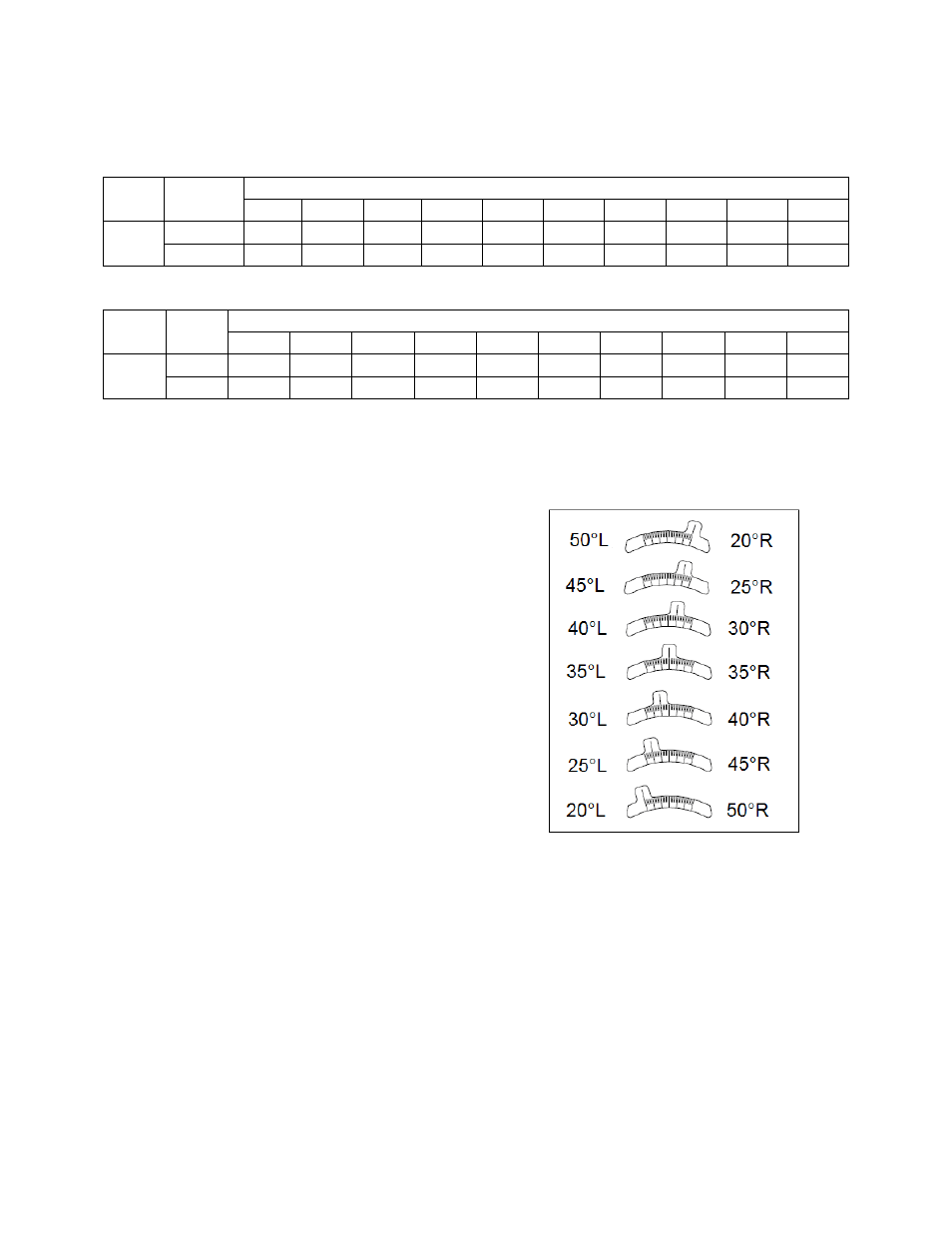
3. Replace the pitch insert in the blade root
with an insert of the desired pitch.
Figure 13 - Pitch Insert
4. Replace blades to their original location.
5. Replace all nuts, bolts, and washers on the
fan hub.
6. Replace retaining plates and center boss
to original location.
7. Tighten nuts and bolts to 14 ft-lbs of
torque.