Operation adjustments, Wiring (continued...) – Delta Controls T01 User Manual
Page 2
002522-SENTRY-C : FEB 2012
www.delta-controls.com
IF
HINGE
IS
DAMAGED,
INGRESS
PROTECTION
LEVEL
COULD
BE
COMPROMISED.
A single M20 or ½”NPT electrical entry is provided,
into which a cable gland can be assembled. Select a
suitable cable gland which will maintain the IP rating of
the instrument.
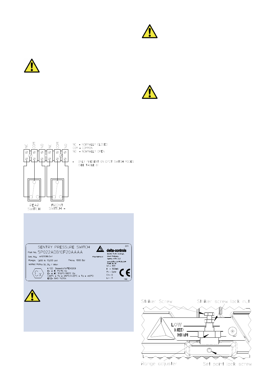
The three switch terminals are clearly marked
“NORMALLY CLOSED”, “NORMALLY OPEN” and
“COMMON”.
For products supplied with terminal blocks, the follow-
ing diagram can be used as a guide for wiring.
Insert bare wires fully into the terminal block and
tighten securely. Keep wiring tails to a minimum and
check that wires do not interfere with the operating
mechanism. Use the earthing / grounding points
provided.
BEFORE CLOSING THE LID:
Ÿ ENSURE WIRE IS CLEAR OF ALL
MOVING PARTS.
Ÿ CHECK THAT THE GASKET IS SEATED
CORRECTLY AND IN GOOD CONDITION
Ÿ ENSURE THAT WIRES DO NOT TOUCH
THE LID AS IT IS CLOSED
Close the lid, being careful not to trap any wires in
doing so. Tighten the lid locking screw until the lug on
the top of the lid makes contact with the enclosure lug.
OPERATION
Adjustments
Pressure and Temperature Switches are supplied
calibrated at the midpoint of their range and to a falling
pressure or temperature unless otherwise specified.
To re-calibrate:
1. Isolate the instrument from the process and power.
2. Loosen lid lock screw and open the lid.
3. Slacken the set point lock screw.
4. Using a suitable spanner, rotate the range
adjuster clockwise to increase the set point and
counter-clockwise to decrease the set point.
5. Tighten the set point lock screw.
6. Close the instrument lid and tighten lid lock screw
Note: For accurate setting of Pressure and Differential
Pressure models, a suitable pressure gauge must be
used in conjunction with the above procedure. Do not
attempt to set the switch outside the scale limits. For
Temperature models a suitable calibrated temperature
source should be used.
Though the unit may be set anywhere within its range,
for optimum performance, it is good practice to have a
set point value between 25% and 75% of span.
The striker screw and lock nut are factory set and
should not be adjusted. Should these parts be acci-
dentally loosened, please contact Delta for assistance.
Wiring (continued...)
Undo the single lid retaining screw and allow the
hinged lid to rest in an open position. Be careful not to
apply excessive pressure on the opened lid to avoid
damage to the hinge.
THE LID LOCKING SCREW MUST BE
TIGHTENED FULLY IN ORDER THAT
ELECTRICAL
CONNECTION
IS
MADE
BETWEEN THE LID AND THE ENCLOSURE
THE MICRO SWITCHES MAY BE SINGLE OR
DOUBLE
POLE,
DOUBLE
THROW
SWITCHES AND ALL THE ELECTRICAL
CONNECTIONS MUST FORM PART OF THE
SAME INTRINSICALLY SAFE CIRCUIT.
WHERE TWO MICRO SWITCHES ARE
FITTED, THEN ALL THE ELECTRICAL
CONNECTIONS MUST FORM PART OF THE
SAME INTRINSICALLY SAFE CIRCUIT.
Notes for Intrinsic Safety
Input limitations for intrinsic safety:
Ui = 30V, Ii = 300mA, Pi = 0.6W
Example label: