CHIEF PWC-2000 User Manual
Page 8
PWC-2000
Installation Instructions
8
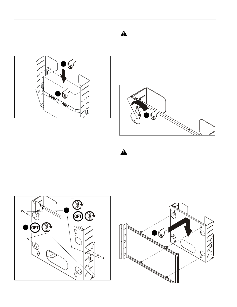
4.
Carefully slide CPU between strap (E) and rear surface of
side plates (See Figure 5). Ensure the following:
•
Both loops of strap (E) are in front of the CPU; do not
wrap strap (E) around back of CPU.
•
CPU is positioned so that cooling vents are not
obstructed.
Figure 5
5.
Tighten strap (E) securely.
6.
Re-install front plate by reversing the procedure in Step 2:
A.
Tilt the top of the front plate towards you.
B.
Lower the front plate onto the lower attach screws.
C.
Tilt the top of the front plate away from you (towards
the wall).
7.
Using key (F), re-install the retained upper front plate attach
screws and washers (See Figure 6).
NOTE:
If desired, security screws (C) may be substituted for
non-security screws at both upper and lower attach
points.
Figure 6
DISPLAY INSTALLATION
WARNING:
Exceeding the weight capacity can result in
serious personal injury or damage to equipment! It is the
installer’s responsibility to make sure the combined weight of
all components attached to the PWC-2000 does not exceed
200 lbs (90 kg).
1.
Install interface providing 14" X 14" (356mm x 356mm)
mounting button pattern to display. See instructions
supplied with interface.
2.
Rotate Q-Latch to the OPEN position (See Figure 7).
Figure 7
WARNING:
Display is very heavy! Ensure display can be
safely lifted and maneuvered as required to install to mount.
Failure to take adequate precautions can result in serious
personal injury or damage to equipment!
3.
Lift and maneuver display so that all four mounting buttons
on interface fit into button openings on front plate. Lower
display firmly into place. Ensure each button has fully
seated in its button opening (See Figure 8).
NOTE:
Display not shown for clarity.
Figure 8
4
5
x2
7
x2
7
x2
2
3