CHIEF JHS Series User Manual
Page 6
JHS Series
Installation Instructions
6
WARNING:
IMPROPER INSTALLATION CAN LEAD TO
DISPLAY FALLING CAUSING SERIOUS PERSONAL
INJURY OR DAMAGE TO EQUIPMENT! Inadequate thread
engagement in display may cause display to fall! Back out
screws ONLY as necessary to allow installation of Centris
cup!
1.
Start two M4 x 8mm Phillips pan head screws (included in
interface bracket hardware kit) into upper mounting holes in
display back. (See Figure 3)
NOTE:
Leave at least 1/8" of each screw protruding out back
of display.
Figure 3
2.
Align two screws in display back with upper mounting holes
in Centris cup and lower display until screws are seated in
lower area of teardrop mounting holes. (See Figure 4)
3.
Install two more of the same screws through lower mounting
holes in Centris cup and into display back. (See Figure 4)
4.
Tighten all hardware.
5.
Route cables and wires to display.
Figure 4
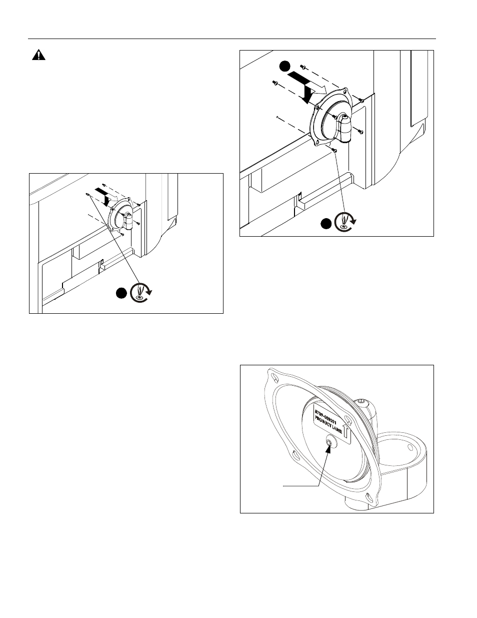
Adjustments
To adjust display Roll, Pitch, and YAW tension:
1.
Disconnect all wires and cable from the display.
2.
Remove two Lower screws securing display to Centris cup.
3.
Loosen two Upper screws securing display.
4.
Lift display upward and away from mount.
5.
Using a hex head wrench turn the tension adjustment screw
clockwise to increase tension, or counter-clockwise to
decrease tension. (See Figure 5)
6.
Re-install display.
Figure 5
x 2
1
x 2
2
3
Tension
adjustment
screw