Cable management, Adjustments – CHIEF FHP110, FHPV User Manual
Page 7
Installation Instructions
FHP110, FHPV
7
Attaching Assembly Columns
CAUTION:
WATCH FOR PINCH POINTS! Do not place
fingers between movable parts.
1.
Slide inner column with attached display up from below into
installed outer column. (See Figure 5)
2.
Secure inner column into outer column at desired height
using 1/4-20 x 1-1/2" socket head cap screw (C),
1/4" x 1/2" x .032" nylon washer (E) and 1/4-20 locknut (D).
(See Figure 5)
Figure 5
Cable Management
1.
Ensure cables are unobstructed and do not run through a
pinch point.
2.
Route power cables against column, allowing sufficient
slack for extension and avoiding pinch points.
3.
Install cable sheath (J) over cables.
4.
Measure distance of remaining exposed cables and, using
a saw or appropriate tool, cut lower cable sheath to length.
5.
Install bottom cable sheath over remaining exposed cables.
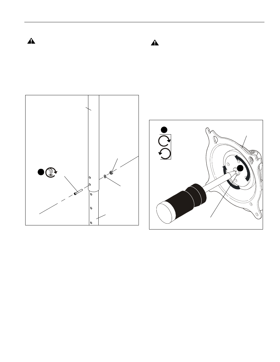
Adjustments
CAUTION:
Watch for pinch points! Do not place fingers
between movable parts.
To adjust display Roll, Pitch, and YAW tension:
1.
Disconnect all wires and cable from the display.
2.
Remove two Lower screws securing display to Centris cup.
3.
Loosen two Upper screws securing display.
4.
Lift display upward and away from mount.
5.
Using a Phillips screwdriver turn the tension adjustment
screw clockwise to increase tension, or counter-clockwise
to decrease tension. (See Figure 6)
6.
Re-install display.
Figure 6
Outer column
Inner column
2
(C) x1
(D) x1
(E) x1
5
Centris cup
Tension adjustment screw
tighten
loosen
5