CHIEF SL151 Series User Manual
Page 8
SL151
Installation Instructions
8
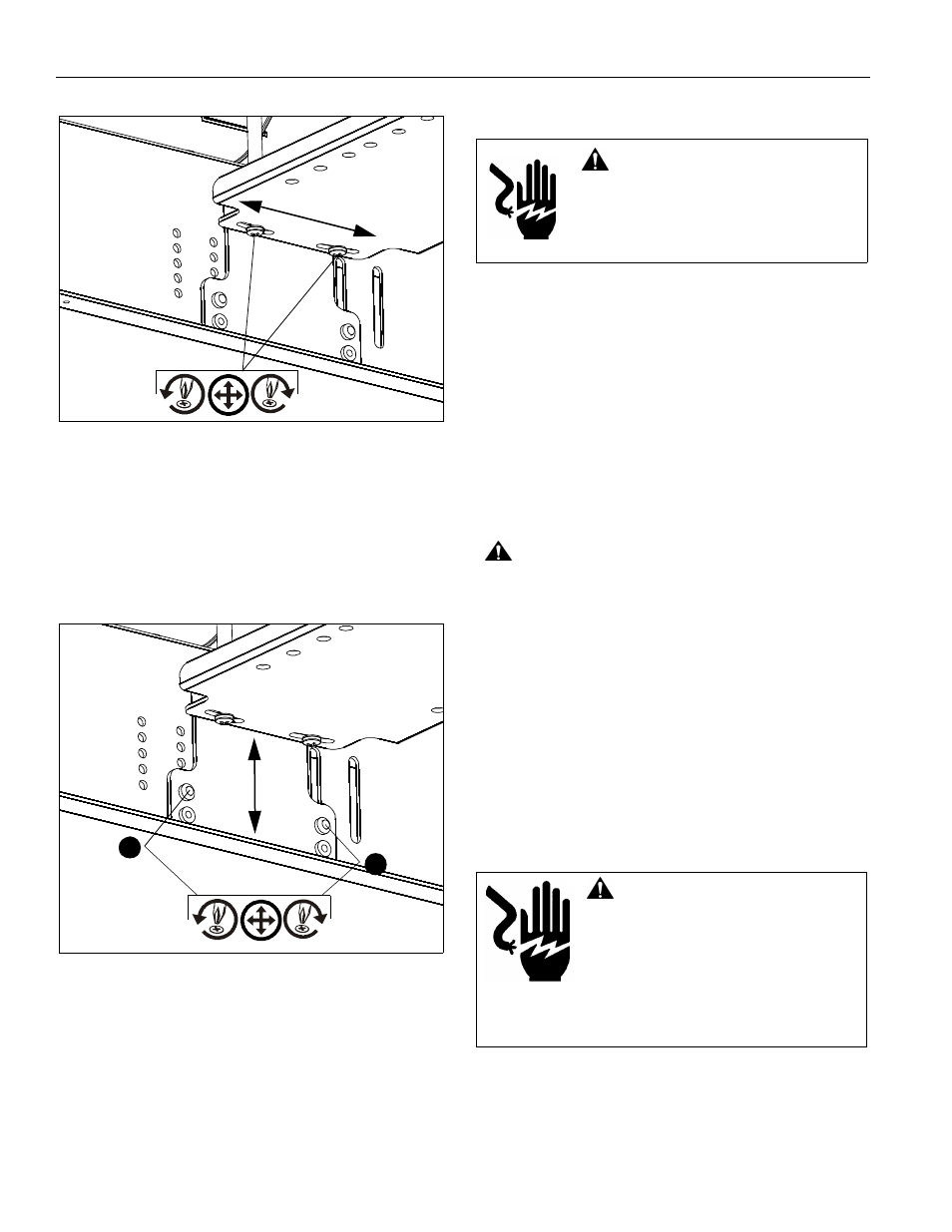
Figure 12
3.
PITCH
•
Remove and save back screw on each side.
•
Adjust vertically, as required.
•
Reinstall and tighten screws. (See Figure 13)
4.
VERTICAL
•
Remove and save front screw on each side.
•
Adjust vertically, as required.
•
Reinstall and tighten screws. (See Figure 13)
Figure 13
5.
ROLL (Horizontal Tilt)
•
Shift bracket up or down in the side holes on one side
or the other by removing screws.
•
Adjust and tighten screws on bracket. (See Figure 13)
Connecting Control Wiring
1.
Unplug the SL151’s test cord (used for testing).
2.
Remove the jumper wire and supplied push button wiring
(previously installed in the Pre-Test Lift before Installation
section) from the external terminal block. (See Figure 3)
3.
Connect control wiring following instructions included with
the controller and information in Table 1: Wiring Table
NOTE:
Any knockouts removed in the SL151 must be
replaced with a supplied rubber grommet (G).
4.
Feed the video and/or communications cables through the
knockout in the rear or top of the lift and connect it to the
projector.
NOTE:
Ensure there is enough slack in the cables to allow for
up and down movement of the lift.
5.
Secure cables as necessary using supplied mounting pads
(E) and cable ties (B).
CAUTION:
KEEP SL151 OPEN WHILE PROJECTOR IS
RUNNING OR IN COOLING MODE! Premature bulb failure
or damage to electrical components may occur if lift closes.
NOTE:
If SL151 is cycled up and down repeatedly the motor’s
thermal overload protection will stop operation.
Operation will resume when the thermal overload
resets (usually within 3 to 5 minutes).
Connecting to Power Supply
IMPORTANT ! :
This product must be connected to a
grounded metal, permanent wiring system, or an equipment-
grounding conductor must be run with the circuit conductors
and connected to the equipment-grounding terminal or lead on
the product.
1.
Disconnect and remove power inlet from interior junction
box.
2.
Hardwire unit to a 120V 60Hz 12-amp power source.
NOTE:
This unit was designed to have conduit run directly into
the back of the interior junction box.
3
4
WARNING:
All wiring should be
performed by a licensed electrician following
the National Electric Code, ANSI/NFPA, and
Canadian Electrical Codes, Part 1.
WARNING:
FAILURE TO
DISCONNECT AND TERMINATE POWER
LEADS PROPERLY MAY RESULT IN
PERSONAL INJURY OR EQUIPMENT
DAMAGE!! Licensed electrician must
disconnect and terminate the leads to the
power cord receptacle, and must hard wire
the SL151 to a 12-amp power source.