CHIEF SL151 Series User Manual
Page 10
SL151
Installation Instructions
10
Table 1: WIRING TABLE
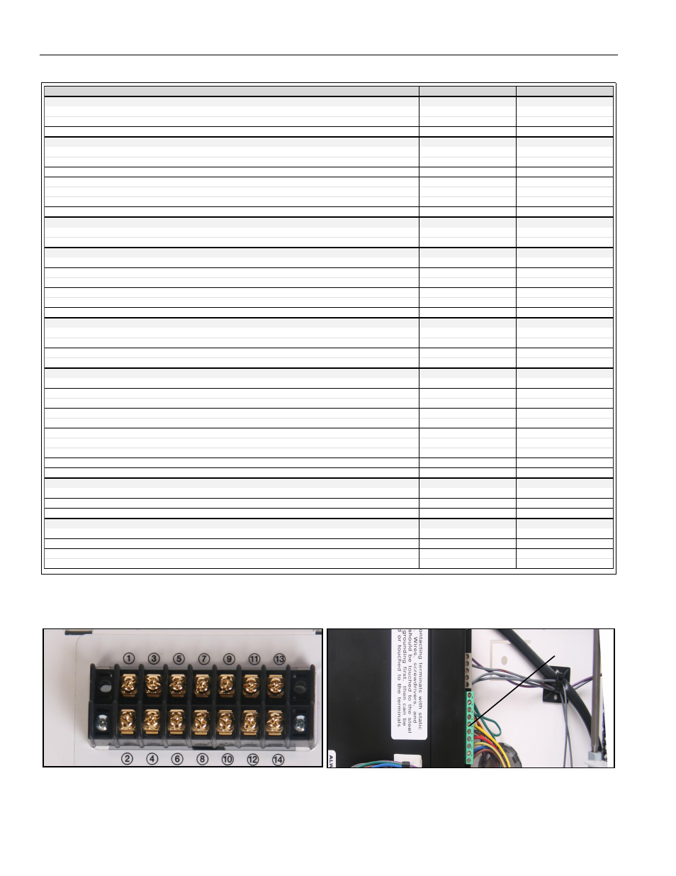
Figure 16
NOTE:
The numbers listed in the SL151 Internal and SL151 External columns refer to the corresponding numbers located where
indicated in the wiring pictures. (See Figure 16)
Accessory\Product
SL-150/151 Internal
SL-150/151 External
Pushbutton (Supplied on some models) (Momentary SPST)
Red 2 (24V AC - Comm)
2 (24V AC - Comm)
Black 6 (Extend/Retract - Comm)
5 (Extend/Retract - Comm)
Other Jumper 1 & 5
Jumper 1 & 6
ASP-401
Up 12 (retract)
3 (retract)
Down 11 (extend)
4 (extend)
Open N/A
N/A
Close N/A
N/A
Left N/A
N/A
Right N/A
N/A
Common 13 (ground)
9 (ground)
12V Trigger (will actually work with 5-30V AC or DC)
12V+ 7 (trigger +)
N/A
Ground 8 (trigger -)
N/A
IR-10
+12V 4 (12V DC)
10 (12V DC)
GND 3 (ground)
9 (ground)
C1 12 (retract)
3 (retract)
C2 11 (extend)
4 (extend)
C3 No Connection
No Connection
COMM 13 (ground)
9 (ground)
RC-10
(radio power) - Red 1 (24V AC)
1 (24V AC)
(relay) - Black 6 (Extend/Retract - Comm)
5 (Extend/Retract - Comm)
(24V) - White 2 (24V AC - Comm)
2 (24V AC - Comm)
Other Jumper 1 & 5
Jumper 1 & 6
Low Voltage Wall Switch or Relay Control
Up 12 (retract)
3 (retract)
Down 11 (extend)
4 (extend)
Service N/A
N/A
Open N/A
N/A
Close N/A
N/A
Sequence (Show Mode) N/A
N/A
Stop N/A
N/A
Left N/A
N/A
Right N/A
N/A
Common 13 (ground)
9 (ground)
Error Reversing (contact between error input and common indicates an error and unit reverses direction)
Extend Error 14 (extend error)
8 (extend error)
Retract Error 15 (retract error)
7 (retract error)
Common 13 (ground)
9 (ground)
Relay Contacts (relay closes when unit reaches end of travel)
Extend Relay a 16 (extend relay in)
14 (extend relay in)
Extend Relay b 17 (extend relay out)
12 (relay out common)
Retract Relay a 18 (retract relay in)
13 (retract relay in)
Retract Relay b 19 (retract relay out)
12 (relay out common)
EXTERNAL WIRING
INTERNAL
WIRING