Zero-Max Control flex Single Disc Clamp Hub Coupling User Manual
Control flex single disc clamp hub, Coupling
Installation Instructions for Control flex Single Disc
Clamp Couplings
1. Tools Required:
Torque wrench with hex socket for clamp hub
socket head cap screws.
Laser alignment tool or dial indicator
(recommended). If not available a straight edge
and feeler gauges.
Caliper
2. These instructions are for standard series couplings
with normal running conditions. Special couplings may
have different instructions or drawings.
3. When initially mounting the coupling, the
misalignment may be one and one half times the
maximum permissible misalignment shown in the
catalog. Inspect hub bores, shafts, and keyways
making sure there are no burrs. Clean hub bores and
shafts. Standard control flex coupling hubs are supplied
with slight clearance fit (see catalog).
.
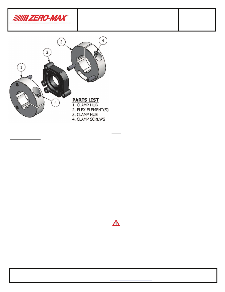
Control flex Single Disc
Clamp Hub
Coupling
4. Install the coupling onto the shafts. It is recom‐
mended that the ends of both shafts be flush with the
end of each hub. If the shaft extends past the hub face
verify there is enough clearance between shaft and flex
disc that the shaft will not contact the flex disc during
operation. Tighten one clamp hub socket head cap
screw to lock the hub onto the shaft. See the table for
the proper tightening torque.
5. Adjust hub separation to dimension “C” specified in
the Table and diagram. Tighten Second hub to the shaft.
6. Align the shafts within the limits for parallel and
angular misalignment specified on page two. For best
alignment results, use a laser alignment tool or dial
indicator.
Note: Aligning the shafts as closely as possible at the
time of initial installation will reduce noise and allow the
coupling extra capacity for misalignments and loads
which will occur during operation over the life of the
connected equipment. Installing and operating coupling
at higher degrees of misalignment is possible (see
catalog ratings), but will generally reduce the life of the
flex disc.
Coupling and shaft alignment should be checked
periodically due to foundation settling, equipment
shifting, etc. Alignment should be re‐checked after the
first several hours of operation.
Caution: Rotating equipment is potentially
dangerous and should be properly guarded. It is the
responsibility of the machine builder, user, or operator
to follow all applicable safety codes and provide a
suitable guard. Make sure the machine is “locked out”
and cannot be accidently started during installation or
maintenance of coupling.
C0xxP-0708-1
13200 Sixth Avenue North Plymouth, MN 55441‐5509 PHONE (763) 546‐4300 FAX (763) 546‐8260
TOLL FREE 1‐800‐533‐1731
www.zero‐max.com